Maximizing Efficiency with Variable Frequency Drives
Discover the advantages of variable frequency drives - matching torque and speed to process requirements, saving energy, and reducing wear. Learn about AC variable drives and torque-speed curves.


Maximizing Efficiency with Variable Frequency Drives
E N D
Presentation Transcript
Need for variable frequency drives • Match the Torque of a drive to the process requirements • Match the Speed of a drive to the process requirements • Save Energy and improve efficiency
Need for variable frequency drives • Smooth acceleration/deceleration to ..... • Reduce mechanical wear and water hammer • Reduce current surges in the power supply system • Energy savings are possible ..... • Most significant with centrifugal pumps and fans because • Power/energy consumption changes with Speed3 • Speed controlled to match the process requirements .... e.g. ... flow or pressure controlled to match demand • Automatic Control of the Process Variable is possible • Closed loop control from a Process Controller
Variable speed – Energy consumption • Principles applied to centrifugal Pumps and Fans
Variable speed – Energy consumption • Compare two methods of speed control in a Motor Car .... • Speed controlled using Drive Control (AB) • Speed controlled by using Load Control (AC)
Common example of VS control • The Motor Car is a common example of VS control • Control Torque to provide Acceleration and Braking • Controls Speed to match the traffic conditions • Controls the use of Fuel • Main controls in a Motor Car are : • Accelerator, which controls the Driving torque • Brake, which adjusts the Load torque • Control System .... the driver
4 – Quadrant drive • 1st QUADRANT ..... Torque is +ve and Speed is +ve • Therefore ..... Power is +ve • Energy transferred from Drive to Load • 2nd QUADRANT ..... Torque is -ve and Speed is +ve • Therefore ..... Power is -ve • Energy transferred from Load to Drive .... Braking • 3rd QUADRANT ..... Torque is -ve and Speed is -ve • Therefore ..... Power is +ve • Energy transferred from Drive to Load • 4th QUADRANT ..... Torque is +ve and Speed is -ve. • Therefore ..... Power is -ve • Energy transferred from Load to Drive .... Braking
Fundamental principles • Power is Rate at which Work is being done by a machine • Power is measured in Watts, or usually kW or MW • Power is product of Torque x Speed • At standstill .... Output Power = Zero • Energy represents the work done over a period of time • Energy is the product of Power x Time • Energy is measured as kiloWatt-hours .... kWh
Torque – Speed curves • Torque, Power & Speed are the most important parameters • Torque-Speed curves illustrate the performance of the VSD • shows the rotational force at various speeds • Power-Speed curves illustrate the performance of the VSD • shows the rate of energy consumption at various speeds • These parameters are all related ... for example the Motor Car • Pressing the accelerator produces more torque .... which provides acceleration and gives more speed .... which requires more power (torque x speed) .... which requires more energy (fuel) (power x time)
Types of variable speed drives • Mechanical Variable Speed Drives • Belt and chain drives with adjustable diameter sheaves • Metallic friction drives • Hydraulic Variable Speed Drives • Hydrodynamic types • Hydrostatic types • Electrical Variable Speed Drives • DC Drive with DC motor • VVVF Converter with AC motor • Slip Control with Slip ring Induction Motor • Cyclo-converter with AC motor • Electromagnetic Coupling or "Eddy Current" Coupling • Servo Drives and Stepper Drives
Principles of AC variable drives • Speed controlled by adjusting the Power Frequency (f) • Synchronous Speed • Actual speed is slower due to the Slip • Actual Speed • Stator field flux () is derived from the supply voltage • Air-gap Flux • Output Torque is product of flux density and rotor current IR • Output Torque
AC Variable speed drive From these equations, the following deductions can be made • Speed is controlled by Frequency AND Stator Voltage • Speed reaches Base Speed when VS = maximum, • Further speed increase reduces the Field Flux • This is known as the Field Weakening range • Torque is dependent on VS • Full torque possible at ALL speeds in normal speed range • But Torque falls to zero at standstill • In the Normal Speed range • Output power increases in proportion to the speed • In the Field Weakening range, • Torque falls in proportion to the speed • Output power of the AC Motor remains constant
AC Variable speed drive • Main Features of the AC Variable Speed Drive • Good control and performance characteristics • AC converter relatively complex and expensive • AC Motor needs no maintenance ... high reliability • Efficiency : Converter ± 97% ... overall AC drive >90%
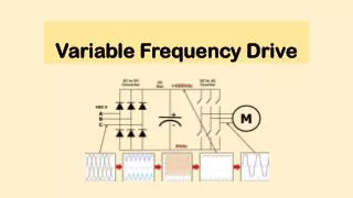
Basic definitions • Rectifier ... AC to DC converter • Inverter … DC to AC converter
Basic definitions • AC Converter converts one AC voltage and frequency to another AC voltage and frequency .... often variable • Usually requires an intermediary DC link with smoothing
Basic definitions • DC Converter ... Converts one DC voltage to another DC voltage • Usually requires an intermediary AC link, such as a transformer
Basic definitions • Electronic Switch ....... • Electronically connects or disconnects an AC or DC circuit • Can often be switched ON or OFF from a gate terminal
Bistable switching • Electronic Switch usually operated in the bistable mode • Blocking Mode : fully switched OFF • Voltage across switch is High • Current through switch is Low (only leakage current) • Conducting Mode : fully switched ON • Voltage across the component is Low • Current through the component is High • Diodes, Thyristors & GTOs are inherently bistable • Transistors are NOT inherently bistable • Must be biased fully ON or OFF to behave like a bistable device
Power diodes IDEAL : Forward Conduction : Resistanceless Reverse Blocking : Lossless Switch on/off Time : Instantaneous • Main terminals are the Anode (A) and the Cathode (K) • Names come from the days when Valves were common • When the anode is positive relative to the cathode • it is said to be forward biased and the diode conducts • When the anode is negative relative to the cathode • is said to be reverse biased and current is blocked
Power diodes • Many different mechanical designs are used • Rated from a few amps … to thousands of amps • Most common is for several diodes to be encapsulated into an Insulated Module ... 6-pulse bridge, half bridge, etc • The base of the module electrically isolated ... Can be mounted directly onto heatsink
Bipolar junction transistor • Main advantage of Bipolar Junction Transistors (BJT) .... • Turned on and off from the base terminal • Suitable for Self commutated inverter circuits • Disadvantage is low base amplification factor .... 5 to 10 • base circuit must be driven by an auxiliary transistor • called the Darlington connection
Field effect transistor • FET is a special type of transistor ... • particularly suitable for high speed switching applications • Gate is voltage controlled .... not current controlled • behaves like a HF voltage controlled resistance • MOSFET is a three terminal device • Source (S), Drain (D) and the Gate (G) • correspond to Emitter (E), Collector (C) and Gate (G) of BJT
Field effect transistor • MOSFET is a majority carrier device .... short switching time • so ... switching losses are low • best suited to high frequency switching applications • With development of Pulse Width Modulated (PWM) inverter • high frequency switching has become a desirable feature • to provide a smooth output current waveform • MOSFETs are used for Small PWM frequency converters • MOS stands for Metal Oxide Silicon. • Ratings from 100Amp @ 50Volt to 5Amp @ 1000Volt
Insulated gate bipolar transistor • Insulated Gate Bipolar Transistor (IGBT) ..... • unites best features of BJT and MOSFET technologies • Construction similar to a MOSFET with additional layer to • provide conductivity modulation, similar to BJT • low conduction voltage drop • IGBT is a three terminal device .... • Power terminals are called Emitter (E) and Collector (C) • Control terminal is called the Gate (G)
Insulated gate bipolar transistor • IGBT has ...... good forward blocking ability • very limited reverse blocking ability • Operates at higher current densities than BJT or MOSFET • Electrical equivalent circuit of the IGBT .... hybrid device • MOSFET driver integrated with a Bipolar PNP transistor
Insulated gate bipolar transistor • Gate driver requirements similar to those of power MOSFET • Turn-on : 10V - 15V takes 1s .... Threshold typically 4V • Turn-off : zero volts takes 2s ... accelerated by -ve volts • IGBT devices can be produced with faster switching times at the expense of increased forward voltage drop • Main advantages of IGBT are : • Good power handling capabilities .... 500A at 1,500V • Low forward conduction voltage drop of 2V to 3V … higher than BJT but lower than MOSFET of similar size • Gate is voltage controlled with low gate current • Relatively simple voltage controlled gate driver • High speed switching capability .... up to about 20kHz • VFincreases with temperature .... making device suitable for parallel operation ... without thermal instability
Overall control system • Overall Control System divided into 4 main areas : • Inverter Control System • Speed Control System and Speed feedback • Current (Torque) Control System and Current feedback • External System Control Interface
Overall control system • Inverter Control System • Controls the Switching Sequence of Inverter Switches • Provides Component Protection • Speed feedback and Speed Control System • Controls the Speed output relative to Setpoint • Current Control System and Current feedback • Controls the Current output relative to Limits • Provides Short-circuit and Earth-Fault Protection • Motor Modelling and Thermal Overload Protection • External System Control Interface • User Settings and Programming • Digital and Analog interface to Control System (PLCs) • Fault Diagnostics
Power supply requirements • Simplest Method for Power Supply ... Mains Transformer • Major problem ... interruption of the Mains Power • VSD Stops ... even for short dips in the supply • Commonly use Switched Mode Power Supplies (SMPS) • Control power maintained until motor stops • Mains failure ... power initially from large DC Capacitors • Thereafter ... motor behaves as AC induction generator • Usually have several Power Supplies to modules such as ... • Device Driver Power Supplies need to be isolated • Cooling fans for the converter heatsinks • DC Link Bus Charging Circuits • Control Cards .... Microprocessor circuits
DC Bus charging • Two main approaches to DC Bus Charging .... • Charging resistors with Contactor Bypass (most common) • Phase-controlled bridge rectifier instead of diode bridge
DC Bus charging - Resistors • Many variations on Charging Resistor theme ... • Resistors can be in DC link or on 3-phase supply lines • Single large resistor or multiple sets of smaller resistors • Electronic Switch instead of Relay ... smaller VSDs • Main Advantages of Charging Resistors are .... • Simplicity of the control circuit • Cheap and easy to implement • Main Disadvantages are ..... • Losses due to relay contacts and coils • Physical size of these components • Reliability of electromechanical devices ... • Can be a problem with numerous starts and stops
Controlled thyristor bridge • Phase-controlled rectifier bridge ... • Used mainly on larger sizes ... above 22kW
Controlled thyristor bridge • Phase-controlled rectifier bridge .... • Capacitor voltage increased gradually • Main Advantages of Controlled Thyristor Bridge are .... • Conduction losses are lower • Physical size reduced by not having the relay • Main Disadvantages are ..... • Thyristors more expensive than Diodes • More complex control circuit • Reactive power requirements are slightly higher • Some VSDs with PWM Rectifier ... other advantages
PWM Rectifier bridge • Controlled PWM Rectifier Bridge ... also called Active Front End • Capacitor DC Voltage increased gradually • Also has other advantages … • Also called ... Active Front End Drive
PWM Rectifier bridge • Main Advantages of PWM Rectifier Bridge are : • Reduces the level of harmonic currents in mains … AC Line current waveform is much smoother • Makes full 4-quadrant operation possible • Can control power factor angle ... power factor correction • Main Disadvantages of PWM Rectifier are ..... • IGBT Bridge is more expensive than Diode Bridge • Control Circuit is more complex and expensive • Require line chokes to limit rate of current rise
PWM Inverter • Output Frequency controlled ... by changing switching speed • Output Voltage controlled ... by changing the Pulse Width • Output Current waveform … depends on load impedance
PWM Inverter • Modulation Technique for sine-coded PWM using the Sine-Triangle intersection method - digital implementation