Download
1 / 30
300 likes | 513 Vues
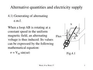
4.1) Generating of alternating e.m.f. When a loop AB is rotating at a constant speed in the uniform magnetic field, an alternating voltage is thus induced. Its values can be expressed by the following mathematical equation: v = V M sin( t ). N. B. v. Flux. A. Fig.4.1.

E N D
4.1) Generating of alternating e.m.f. When a loop AB is rotating at a constant speed in the uniform magnetic field, an alternating voltage is thus induced. Its values can be expressed by the following mathematical equation: v = VM sin(t) N B v Flux A Fig.4.1 Alternative quantities and electricity supply Week 14 to Week 17
If we plot the equation with the time scale, we get the following waveform diagram ( Fig. 4.2): v Vm 360 sin( t ) peak-to-peak 180 period Fig. 4.2 Week 14 to Week 17
i) Instantaneous voltage or current ( v or i ) mean the values of voltage or current at any instant in time (denotes as t). 4.2) Amplitude, period, frequency ii) Alternating current means sinusoidal current and normally abbreviated to a.c. iii) Peak value is the maximum value of the waveform. This is also called as the amplitude of the waveform, sometimes it may call the maximum of the waveform and it always denotes as Vm or Im. iv) Peak-to-peak value is the vertical distance between the positive and the negative peaks. Week 14 to Week 17
v) Frequency, f It is the number of cycles performed in one second and is measured in Hertz (Hz). i.e. 50 Hz = 50 cycles per second. vi) Period, T It is the time for one complete cycle and is measured in seconds. T=(1/f ), for 50Hz, T=(1/50) = 20 ms. vii) Angular velocity, ω (ω=2πf also), is the measured angles per unit of traveled (unit in radian/sec) and (ωt)=θ is the angle between the conductor and the magnetic field at any instant of time. Week 14 to Week 17
4.3) Average and r.m.s. values Let us first consider the general case of a current the waveform of which cannot be represented by a simple mathematical expression. For instance, the waveform shown in Fig. 4.2. Week 14 to Week 17
i i3 i2 i4 i1 t in i7 i9 i8 Fig.4.4 For a pure sinusoidal wave, Iav = 0.637 Im Vav = 0.637 Vm Week 14 to Week 17
In a.c. work, however, the average value is of comparatively little importance. This is due to the fact that it is the power produced by the current that usually matters. Thus, if the current represented in Fig.4.4 is passed through a resistor having resistance R ohms, the heating effect of i1 is (i1)2R, that of i2 is (i2)2R etc., as shown in Fig. 4.5. Therefore, the average heating effect in half-cycle is : Week 14 to Week 17
So, Ir.m.s. = root-mean-square of the current For a pure sinusoidal wave, Ir.m.s. = 0.707 Im Vr.m.s. = 0.707 Vm Week 14 to Week 17
Heating effect r.m.s. value (i8)2 (i3)2 (i7)2 (i4)2 (i2)2 (i9)2 t Fig. 4.5 Week 14 to Week 17
Electrical power transmission & distribution systems in Hong Kong Energy 1.Energy in form of coal, gas, fuel etc is applied to power station. 2.Energy is converted from thermal into electrical energy by generator. 3.Electrical energy is transmitted from power station to urban area by high voltage system, 400kV for CLP and 275 kV for HKE. Electricity Transmission 4.The high voltage is stepped down to three phase 132kV by step down transformer at urban area. 5.The 132kV is further stepped down to three phase 11kV by step down transformer when supply to small industries or commercial buildings. Electricity Distribution 6.Further stepped down to three phase 380V and 220 V a.c. single phase supply is transmitted to household clients by low voltage cables. Fig. 4.6 Week 14 to Week 17
Line voltage and phase voltage: When supply is obtained from the public electricity supply company, the voltage falls into one or more of the following: (i) 220V ±6% single-phase : Current demand does not exceed 60A single phase; No 3-phase equipment installed; (ii) 380V ±6% three-phase 4-wire : Current demand exceeds 60A single phase; There is 3-phase equipment installed; (iii) 11kV +10% or -2.5% three-phase : The load current is very large, and this voltage is supply by special approval from electric company; A special three-phase equipment, such as 11kV motors, is installed. (iv) Three phase 132kV +10% or –2.5% : this is similar to case (iii). The standard current is a.c. and the standard frequency is 50Hz ±2%. Week 14 to Week 17
Distribution Network System • Two basic system are adopted for electricity distribution to household consumers or small industries. They are : • a) Radial System • - The main feature of the system is that the feeders, • distributors and service mains radiate outwards from • the station. • - A fault on any feeder or distributor cuts off the supply • from all consumers who are on the side of the fault • away from the station. Week 14 to Week 17
F1 C Q P F2 C Sub-station C C C Fuses or circuit breaker C C C = consumer Fig. 4.7 Radial feed system Week 14 to Week 17
R F1 Sub-station C Q P F2 C Sub-station C C Sub-station C Fuses or circuit breaker C C = consumer C Fig. 4.8 Ring feed system b) Ring System - Each consumer is supplied via two feeders. If there is a fault on a feeder at F1, the section between Q and R can be switched out without interrupting the supply to the consumers other than between section Q-R. Week 14 to Week 17
Ring feed system against Radial feed system • Advantages • Higher security of supply. • Better voltage regulation. • Loss minimized. • Disadvantages • More careful design is necessary in order to avoid overloading • of any section during outage of the order. • Switching in and out of any section will cause change in the • load distribution of other section thus operational restriction is • imposed. • More complex protection scheme required. • Less versatile for further development. Week 14 to Week 17
220V Live From step-down transformer (Light bulb, Fan, or TV set) Load 0V Neutral Types of electricity supply systems (i) Single-phase (2-wire system) Week 14 to Week 17
3-phase step-down transformer output windings R R B 3-phase load Y N (3-phase motor) B Y Neutral (ii) Three-phase (4-wire system) Phase voltage: Vp = VRN = VYN = VBN = 220V Line voltage: VL = VRY = VRB = VBY = Week 14 to Week 17
4.5 Electric shock (ii) Current exceeds about 16mA for men and 10mA for women will cause stiffening of muscles and prevents a victim of having electrical shock from letting go. (i) Occasionally, a value of 0.5mA current pass through human body will be felt. Electric shock is the electric current that can hurt or kill a person by flowing through the body. The main effects that the flow of electric current produces on the human body may be classified in the sequence of seriousness as: Week 14 to Week 17
(iv) For shock duration below 0.1 second, with a current over 500mA or 50mA for 1 second or 40mA for 3 seconds may cause malfunction of heart. (v) A shock current of 1A may cause heart failure. (iii) When electric shock for a period of 4 minutes, the shock may affect the nerve center that governs movements of muscle. (vi) Heat will be generated when current flow through a resistance. A few amperes current passing through the human body will cause extensive destruction of tissues, breakage of the arteries, destruction of nerve center, etc. Week 14 to Week 17
4.6 Importance of protection and earthing (i) Protection Electrical equipment shall be mechanically and electrically protected to prevent danger from shock, burn, or other injury to person or damage to property or from fire of an electric origin. Electric shock protection is a combination of protection for an electrical installation against both direct and indirect contacts of live parts. A person can receive electric shock in two ways: Week 14 to Week 17
(b) by indirect contact, i.e. touching metallic parts that have become live due to an insulation fault. (a) by direct contact, i.e. coming into contact with live parts, at the same time also in contact with earth potential or alternatively with another live part of a different potential, and Week 14 to Week 17
Protection against Direct Contact (a) protection by insulation of live parts; (b) protection by barriers or enclosures; (c) protection by obstacles; (d) protection by placing out of reach. In practice, an electrical installation involves the use of a combination of above methods. Week 14 to Week 17
Protection against Indirect Contact • a) protection by earthed equipotential bonding and • automatic disconnection of supply, abbreviated • EEBADS; • b) protection by double or reinforced insulation; • c) protection by non-conducting location; • d) protection by earth-free local equipotential • bonding; • e) protection by electrical separation. Week 14 to Week 17
Overcurrent protection: Overcurrent protection is essential that the vital relation between effective overcurrent protection and the safety of personnel and property must be fully recognized. Careful and adequacy in selection of overcurrent protection can both prevent shock and fire hazards and maintain reliable life of equipment and systems. Week 14 to Week 17
An overcurrent is defined as a current exceeding the rated value of a circuit or the current-carrying capacity of a conductor. Overcurrent may occur in a healthy circuit by connecting excessive loads to it or due to surges. The resulted current is called overload current. Overcurrent may also be caused by a fault of low impedance between live conductors having a difference in potential or between live conductors and exposed or extraneous-conductive parts under normal operating conditions. The currents thus flow are called short-circuit current and earth fault current respectively. They are collectively known as fault currents. Week 14 to Week 17
Every circuit shall be protected against overcurrent by one or more devices which will operate automatically and timely to interrupt the supply in the event of an overcurrent to ensure no danger is caused. The following devices are suitable for protection against both overload and fault current provided that they are capable of breaking and, for a circuit-breaker, making any overcurrent up to and including the prospective fault current at the where the device is installed: • Fuses, • Miniature Circuit Breakers (MCB); • Moulded case circuit breakers (MCCB); Week 14 to Week 17
Circuit breakers incorporating overcurrent release in the • form of integral thermal-magnetic trip device, electronic • trip device, or external overcurrent relays; • Circuit breakers in conjunction with fuses. • Earthing • The objective of earthing is to provide a low impedance path for the earth fault current to discharge without danger when metalwork of electrical equipment other than current-carrying conductors may become charged with electricity. The earthing of an installation must be: Week 14 to Week 17
Continuously effective; • Capable to carry the earth fault and earth leakage • currents without danger; • Robust, or having additional mechanical protection; • Arranged to prevent damage to other metallic parts through electrolysis. Week 14 to Week 17
Earth-fault current, Ia L Touch voltage Z 1 Vt N E Z 2 Z E Earth-fault loop impedance equals to the total impedance from terminal L to earth. Week 14 to Week 17
Although a proper earthing and bonding are used in electrical installation, protection against indirect contact should also be considered. Protective device for automatic disconnection should be used, such that during an earth fault the voltage between simultaneously accessible exposed-and extraneous-conductive-parts are not to cause danger. • The protective device may be either: • an overcurrent protective device, or • a residual current device (which is a preferred method whenever the prospective earth fault current is insufficient to cause prompt operation of the overcurrent protective device) Week 14 to Week 17