Interrupts
An interrupt is an electronic signal that indicates an event has occurred, causing a deviation in the normal execution flow of a program. It was first introduced with the Atlas computer to enhance concurrency by allowing I/O devices to signal when service is needed, rather than the CPU polling constantly. This article explores how interrupts work, including the role of interrupt handlers, the importance of saving program status during interrupts, and the different types of interrupts - hardware and software. Efficient management of interrupts ensures smooth process transitions and reliable computing operations.


Interrupts
E N D
Presentation Transcript
Interrupts And tips for R3
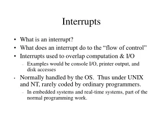
What is an interrupt? An interrupt is an electronic signal that indicates an event (possibly caused by hardware or the program its self) has occurred which results in a deviation from the normal flow of execution in a process. In the normal flow of events, when a process is executing a program, execution proceeds sequentially from one statement to the next, unless a branching statement is encountered. The concept of interrupts was introduced, with Atlas, and used to provide some concurrency in computing by allowing I/O devices to proceed with data transfers while the CPU performed other tasks instead of constantly polling the I/O device. An interrupt facility allows the I/O devices to signal the system only when service of some type is required. Also interrupts are used to enable the system to keep track of the time of day and set alarms to time specific events.
#include <stdio.h> int main(void) { int I; int sum=0; for (i=0; i<=10; i++){ sum=sum+I; } printf(“the final sum is %d\n”, sum); } When an interrupt signal occurs, execution in the original program is suspended, the status of the program saved, and control is transferred to a special routine called an interrupt handler that processes the interrupt, and then calls the dispatcher. The original program may then resume execution, or another may belaunched Normal flow is sequential “the interrupt handler”
When an interrupt occurs • The currently executing program is temporarily suspended. • The context/status of the process is saved • Control shifts to a special routine called an interrupt handler. • An interrupt handler is: • A specially written routine whose job is to evaluate the cause of the interrupt • Perform any special tasks associated with the interrupt • Return control back to the previously executing program at the EXACT statement which would have normally been executed if the interrupt had not occurred. • OR to trigger a context switch to give control of the CPU to a different program/process. • One of the most critical issues with respect to managing interrupts is that the COMPLETE status of the suspended process must be correctly saved and restored.
Interrupts can originate in either hardware or software. • Programs issue interrupts to request the operating system’s support • Hardware issues interrupts to notify the processor that an asynchronous event has occurred.
For Example: A program might use a system call to generate an interrupt to signal that it needs data: (Example taken from Operating Systems, a systematic view, by Davis & Rajkumar) The running program A requests input data, this triggers an interrupt, and control transfers to the interrupt handler Operating System PCB’s Program State A running B ready Dispatcher channel Interrupt Handler Routine disk
The interrupt handler sets the running process to the blocked state, and begins execution. Operating System PCB’s Program State A blocked B ready Dispatcher channel Interrupt Handler Routine disk
The interrupt handler, calls the I/O control system, which starts the I/O operation, before returning control back to the dispatcher Operating System PCB’s Program State A blocked B ready Dispatcher channel Interrupt Handler Routine disk
The I/O controller will continue with the I/O operation while the dispatcher launches another process. The I/O controller may generate multiple interrupts depending on whether information is transferred character by character or as a block. Operating System PCB’s Program State A blocked B running Dispatcher channel Interrupt Handler Routine disk
When the operation is complete, the channel issues an interrupt, and once again the interrupt handler begins executing, the waiting process will be unblocked, and again the dispatcher is called Operating System PCB’s Program State A blocked B running Dispatcher channel Interrupt Handler Routine disk
What types of interrupts may occur? Essentially there are 4 types of hardware interrupts, and 2 types of software interrupts. • I/O Interrupts: • Generated by I/O devices (via the device interface) • These indicate that service is needed from a software interrupt handler: • Transferring another character to or from a character by character device • Servicing the completion of a total I/O request (block of data being read or written) • Handling of an error condition in the device (paper jam)
Alert Interrupts • These result from unexpected conditions outside the computer system • Some keyboards contain an “interrupt key” which can be used to activate the command handler • Or in a Multiprocessor system when one CPU signals another to signify some condition or service request from the other CPU
Timer interrupts: • Generated by internal software timers • Can be used to indicated that the last unit of time placed into a timer has expired, which indicates that some activity is to occur. (running process is to be preempted when the CPU time limit expires) • Interrupts may be generated at regular intervals by a hardware clock • Each interrupt means that another fixed fraction of time has expired and that the software clocks should be updated.
Machine fault interrupts • Indicate that a hardware error has occurred • Memory fetch error • I/o device error • These interrupts typically can not be masked or ignored. • Many OS’s simply report these errors and terminate • Others, if resources permit, try to isolate the offending hardware and try to continue execution.
Software generated interrupts • Software Interrupts are usually implemented as instructions in the instruction set which cause a context switch to the interrupt handler similar to a hardware interrupt • System request interrupts: • Result when processes request service from the OS through the use of special instructions which generate a system request interrupt. • The system call instruction is provided via the OS’s program interface • Execution of this command causes a transfer of control to the OS • Parameters may be used to transfer arguments to the OS, identifying the type of service requested. • The OS will analyze the request, possibly blocking the process requesting the service until the service is complete.
Program Fault Interrupts • Abnormal conditions that arise within the running program • Divide by zero • Underflow/overflow during an arithmetic operation • Invalid memory reference • For these category of interrupts users can supply the address of a special routine to execute when the error occurs otherwise the OS will execute a default routine (typically reporting the error and terminating execution of the program)
Software interrupts (or exceptions) are synchronous interrupts which are generated when the processor detects a predefined condition, such as division by 0. The exception occurs during the machine cycle which is driven by a clock tick, and since they are caused by the program itself there is a precise point within the program at which the transfer of control to the interrupt handler should occur. • Others are Asynchronous because even though they should be serviced ASAP, the exact point at which the program should be interrupted isn’t predetermined.. May be immediately after the execution of the current machine instruction (at the next clock tick), or later. These are raised by hardware devices at unpredictable times.
Interrupt Generation • Many interrupts begin as a signal sent to the processor when an event occurs. (interrupt-request line) • Usually the interrupt signal is recorded when it occurs by setting a flag (bit) in a special processor register (program status word). The # of actual flags vary from architecture to architecture, sometimes multiple interrupts must share the same flags.
Once the interrupt is “raised” it is the job of the CPU to “catch” the interrupt, interpret it, and “dispatch” the appropriate interrupt handler. The handler then “clears” the interrupt by processing the request (clearing the flag). • To successfully manage interrupts we need 3 facilities • The ability to defer interrupt handling during critical processing. • We need an efficient way to dispatch to the proper interrupt handler without polling every device to see which one initiated the interrupt • We need multilevel interrupts so that the operating system can service interrupts in order of importance if multiple interrupts occur simultaneously.
Dispatching the interrupt handler • When an interrupt occurs we need to transfer control immediately to the appropriate interrupt handler. • When this transfer occurs it is CRITICAL that some capability is provided to save the status (context) of the executing process. • The contents of every CPU register and the status flags must be saved (possibly on the current stack) so that they can be restored when the suspended process is resumed.
IF interrupt THEN save execution address (PC) save status information transfer control to interrupt handler END
The exact transfer mechanism varies slightly from architecture to architecture but most associate each interrupt with a small data structure in “low memory” called an interrupt vector. This structure contains: • The address of the Interrupt handler • (maybe) a location to store the return address and the status of the interrupted program.
FOR EXAMPLE: • In MS-DOS, interrupt processing uses an interrupt vector table that occupies the first 1K bytes of memory. (Example taken from Operating Systems, a systematic view, by Davis & Rajkumar) • Most of the actual routines are found in IO.sys or MSDOS.sys
The interrupt consists of an electronic pulse and the address of an interrupt vector. Instruction pointer When the interrupt occurs hardware immediately copies the instruction pointer register (and a few other registers) to the stack! It then loads the starting address specified in the interrupt vector into the IP. With the next machine cycle the first instruction in the interrupt routine is fetched. Once the interrupt is processed, the contents of the stack are copied back into the IP and the original program resumes processing. stack
A fully vectored interrupt mechanism provides a distinct interrupt vector for each interrupt. This reduces the need for a single interrupt handler to search all possible sources of interrupts to determine which one needs service.
IBM-PC is fully vectored. With distinct interrupt vectors for each interrupt IF interrupt THEN save execution address (Program Counter) save status (Program Status Word) CASE interrupt IS WHEN device1: transfer control to device1 interrupt handler WHEN device2: transfer control to device2 interrupt handler WHEN device3: transfer control to device3 interrupt handler WHEN device4: transfer control to device4 interrupt handler ENDCASE ENDIF /* In this case the cause of the interrupt can be determine without further program execution */
Other architectures allow multiple interrupts to share the same interrupt vector, by creating a limited set of interrupt categories: IBM/370Here control passes to the same first level interrupt handler, which must then test an addtional special register to determine which device caused the interrupt. FLIH: save registers read interrupt_status_register CASE interrupt_status_register IS WHEN device1: call device1_SLIH WHEN device2: call device2_SLIH WHEN device3: call device3_SLIH ENDCASE restore registers RETURN from interrupt
Ordering of Interrupts by priority • Typically different categories of interrupts are assigned designated priorities. • This allows the CPU to defer the handling of low-priority interrupts without masking ALL interrupts • Makes it possible for a high priority interrupt to preempt the execution of a low priority interrupt. • If interrupts are masked it is imperative that interrupts be unblocked as soon as possible. • IE: The interrupts for an I/O device can be turned off while servicing an interrupt for that device.
Structure of an Interrupt handler • There are several ways in which the structure and design of an interrupt handler must be different than that of an ordinary procedure:
A linkage must be created between the physical interrupt and the handler, so that the handler will be invoked when the interrupt occurs: • Each interrupt handler is linked to the appropriate physical interrupt by storing its starting address in the associated interrupt vector location. • During system initialization the OS is responsible for setting up the interrupt vectors with the address of default interrupt handlers • When the interrupt occurs special hardware mechanisms access the contents of the vector, perhaps save some brief status data, and transfer to the specified handler
2) Since interrupts may occur at unpredictable points in program execution, the complete system state must be preserved during interrupt handling. This means that after the interrupt the content of all machine registers must be exactly as before; moreover, all memory used by the running process, including "hidden" areas such as a stack, must be undisturbed. • Save all registers which could be modified by the interrupt handler onto the stack or in a private memory area. • The hardware itself may save some critical registers such as the status register along with the return address. • The handler software is then expected to immediately save all other registers that might be used. • At termination of the handler the software must restore all registers save by software and the hardware restores those saved by hardware.
3) Parameters cannot be passed to an interrupt handler in the usual way • Interrupt handlers are not called via the normal call mechanism, so parameters can not be passes via the normal mechanism • If an handler requires data to be passed into it, then that information must be placed in a special place such as a special register or on the stack.
4) Because interrupt handling is a temporary deviation from the normal execution of a running process, the handler may be severely restricted in the resources it may use, and in the subprograms it may call • The interrupt handler should not make use of resources that could be allocated to another process. They should not normally access data files or I/O devices. Nor should they allocate memory or use any memory other than their own.
5) Interrupt handlers must allow for the appropriate handling of other interrupts while the handler is in progress. • Typically a computer many need to process thousands of interrupts per second • When an interrupt occurs, the hardware automatically disables other interrupts. This is necessary to avoid confusion during the initial saving of the system state. • Interrupts should be re-enabled as soon as possible. • IF the interrupt handler is VERY short then interrupts may be left disabled until the handler terminates
6) Interrupt handlers must complete their work in the shortest possible time, leaving more complex follow up tasks to other system or application software. • The interrupt handler should complete its work and terminate in the shortest possible time. • In many cases it should do as little as setting an event flag which subsequent software could review and process.
7) Interrupt handling is subject to errors that are hard to reproduce, and cannot often be debugged by normal means. • The timing of interrupts is often not repeatable. • Sometimes only in the certain ordering of interrupts do problems occur and can be difficult to solve because the exact ordering of interrupts can not be easily observed or repeated.
Tips for R3: Process Initialization • When we create processes to represent our 5 test procedures we must correctly initialize its context by placing values into its stack, data segment and extra segment.
1) We need to define a special global structure to represent the “context” of a process which is automatically saved onto the processes stack when the process is interrupted: typedef struct context { unsigned int BP, DI, SI, DS, ES; unsigned int DX, CX, BX, AX; unsigned int IP, CS, FLAGS; } context; context *context_p;
Recall that: • When an interrupt occurs the HARDWARE saves the flags register (PSW), CS (code segment), IP (instruction pointer) onto the stack in this order!!!!! • Next because of the interrupt keyword being specified in the implementation of our interrupt handler: void interrupt sys_call_handler() • Assembler instructions will be added to the routine to automatically save the following registers onto the stack: AX, BX, CX, DX, ES, DS, SI, DI, AND BP • Code will also be automatically added at the end of the routine to restore these!!!!!
We need to set up the initial context of each process by initializing the contents of its stack. • The declaration of the PCB should contain a pointer to a stack of size 1k, which should initially be initialized to all zeros!! The stack pointer should be initialized to the “highest” address in your stack (stack address +1024) (remember that the stack grows from high memory down.) • We need to store the initial context of the process in the top portion of the stack!
Pcb.stack_p = pcb.stack_base + pcb.stack_size – sizeof(context); Context_p = (context *)pcb.stack_p; context_p->DS = _DS;context_p->ES = _ES;context_p->CS = FP_SEG(&testn_R3);context_p->IP = FP_OFF(&testn_R3);context_p->FLAGS = 0x200
Process cause interrupts by: • Each process will voluntarily give up control of the CPU using a call to “sys_req” which will generate a system call interrupt. Processes call “sys_req” with two possible op_code values: • IDLE: which will return the process to the ready queue • EXIT: which is a request to terminate the process, and free the PCB. • This call to sys_req will result in an interrupt being generated which should be processed by our “sys_call_hander”
Setting up “sys_call_handler” • During initialization you must set the “sys_call” vector to contain the address of your interrupt handler. It has the prototype: int sys_set_vec (void (*handler)()); The single parameter handler is a pointer to your system call handler. If your handler has the name sys_call, then it should have the prototype: void sys_call (void); Your call to sys_set_vec, which should occur during initialization, will have the form sys_set_vec(sys_call);
Sys_req passes a single parameter to your sys_call_handler, via the stack (previous stack contents) Buffer length pointer parameter (*count) Buffer address parameter (*buffer) Device_id parameter Op_code parameter Flag CS IP AX BX CX DX ES DS SI DI BP We will need to retrieve the contents of the 1st four parameters to identify the type of request made by the calling process.
To access these parameters we define another structure similar to the “context” structure: typedef struct params {int op_code;int device_id;byte *buf_addr;int *count_addr;} params;
We gain access to the op_code by: The stack structure must be a named type. A pointer to this structure is also required: params *param_p; Finally, the following assignment will set the pointer to the address of the actual stack frame to be accessed: param_p = (params*)(MK_FP(_SS,_SP) + sizeof(context)); It is now possible to refer to the op_code value as param_p->op_code.
We then need to interpret this code and take the appropriate action! • First save a copy of the SS and SP and switch to another temporary stack. (local variables should be declared as static) #define SYS_STACK_SIZE 200 byte sys_stack[SYS_STACK_SIZE]; unsigned short ss_save; unsigned short sp_save; unsigned short new_ss; unsigned short new_sp; /* in syscall*/ ss_save = _SS; sp_save = _SP; new_ss = FP_SEG(sys_stack); new_sp = FP_OFF(sys_stack); new_sp += SYS_STACK_SIZE; _SS = new_ss; SP = new_sp;
set param_p point to the correct place: cop->stack_ptr = (unsigned char *) MK_FP(_SS, _SP);param_p = (params *)(cop->stack_ptr + sizeof(context)); • if parm_p->op_code is IDLEchange the state of cop to readyinsert cop to ready queue by priority • else if param_p->op_code is EXITdelete the pcbset cop to NULL • else set context_p->AX to error code. • call dispatch()
In the dispatcher • Automatically saves the data registers onto the temporary stack for the calling process • Then a complete outline for the dispatcher is:
if sp_save is null, ss_save = _SS sp_save = _SP remove the PCB at the head of the ready queue if a PCB was found set cop to this PCB set _SS and _SP to the PCB's stack pointer else set cop to NULL set _SS to ss_save set _SP to sp_save end if "return from interrupt"