Interrupts
Learn the fundamentals of interrupts in embedded systems, including handling, saving context, disabling, and optimizing interrupt latency. Examples and solutions for shared-data problems included.


Interrupts
E N D
Presentation Transcript
Slides created by: Professor Ian G. Harris Interrupts • Embedded systems often perform some tasks which are infrequent and possibly unpredictable • Hang up a VOIP phone when receiver is dropped • Apply brakes when brake pedal is pressed • Regular tasks must be temporarily stopped to deal with the event • Interrupts are the unusual events • Interrupt handlers, or interrupt service routines, are programs which perform necessary tasks
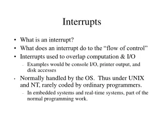
Slides created by: Professor Ian G. Harris Interrupt Handling • Interrupt can be invoked at any time • Regular code must stop for a while
Slides created by: Professor Ian G. Harris Saving and Restoring Context • Interrupt should not interfere with normal tasks • Need to save all used registers at the beginning and restore them at the end • Stack is typically used for temporary storage • Last in, first out (LIFO) • push, pop
Slides created by: Professor Ian G. Harris Disabling Interrupts • Some events should be ignored completely • Some tasks are time-critical and should not be interrupted • X-ray emitter in radiation therapy • Interrupts can be disabled (usually by setting a register) • Nonmaskable interrupt cannot be disabled • For critical events (like loss of power)
Slides created by: Professor Ian G. Harris Interrupt Vectors • Interrupt vector is a pointer to an interrupt in memory • Interrupt number is used to index the table • Interrupt vector table holds pointers to all interrupts • Table location may be fixed or placed in a known register
Slides created by: Professor Ian G. Harris Shared-Data Problem • Interrupts should not change data that the another task is using Main Task Interrupt R1 = 3 + 5; R1 = R1 / 2; print R1 R1 = R1 + 1 • Saving and restoring registers helps • Cannot do the same for memory - Hard to predict which locations to save
Slides created by: Professor Ian G. Harris Shared-Data Example • Main task checks two temperatures to make sure they are equal • Interrupt reads the two temperatures periodically • Interrupt can make the temperatures seem out of sync • Bugs are intermittent
Slides created by: Professor Ian G. Harris Shared-Data Fix? • Maybe problem can be fixed • Place read and compare on same line • No, assembly does not match C code
Slides created by: Professor Ian G. Harris Shared-Data Solution • Identify each critical region where interrupts could be disruptive • Identify code regions that use memory written by an interrupt • Reading more than one address can lead to inconsistency • Disable interrupts before the region, enable interrupts after
Slides created by: Professor Ian G. Harris Shared-Data Solution Example • Critical region is where temps are both read by main task • Data reading is “atomic”
Slides created by: Professor Ian G. Harris Nested Critical Regions void functionA(void) { disableInterrupts( ); --- enableInterrupts( ); } void functionB(void) { disableInterrupts( ); --- functionA( ); --- enableInterrupts( ); --- some code which may be interrupted } • Critical regions inside function calls can conflict • functionA terminates the critical region of functionB early
Slides created by: Professor Ian G. Harris Possible Nesting Solution • Code can check to see if interrupts are disabled before disabling and then enabling them. void functionA(void) { if (InterruptsDisabled()) dis=0; else dis=1; if (dis) disableInterrupts( ); --- some code which must not be interrupted If (dis) enableInterrupts( ); }
Slides created by: Professor Ian G. Harris Another Nesting Solution int DisableCnt = 0; void functionA(void) { MyDisable(); --- some code MyEnable(); } void MyDisable() { disableInterrupts(); DisableCnt++; } void MyEnable() { DisableCnt--; If (DisableCnt == 0) enableInterrupts(); } • Could use a counter in Enable/Disable routine keep track of “levels” of disabling. • Enabled only when all counts are zero.
Slides created by: Professor Ian G. Harris Interrupt Latency • How quickly does the system respond to an interrupt? Contributing Factors: Maximum length of time when interrupts are disabled Time required to execute higher priority interrupts Time between interrupt event and running interrupt code Time required to complete ISR code execution
Slides created by: Professor Ian G. Harris Reducing Interrupt Latency • Make interrupt code short • Reduces ISR execution time and time for higher priority interrupts • Reduce time during which interrupts are disabled • Minimize size of critical regions
Slides created by: Professor Ian G. Harris Interrupts in the ATmega • Many possible interrupt sources • One interrupt vector for each source • Interrupt vector table shown in datasheet, Table 13-1 • Source+”_vect” is the interrupt name recognized by your compiler • Check notes on this (avr-libc manual)
Slides created by: Professor Ian G. Harris Enabling/Disabling Interrupts • ATmega contains a status register called SREG • Bit 7 of SREG , the I bit, is the Global Interrupt Enable • Clearing I bit disables interrupts, setting I bit enables them • I bit is automatically cleared when an interrupt starts, set when interrupt is done • Interrupts are not interrupted • Use the SEI() and CLI() macros to set and clear in C
Slides created by: Professor Ian G. Harris Defining Interrupts in C ISR(vector_name) - Defines an ISR for vector_name. Updates interrupt vector table automatically. Ex. ISR(ADC_vect) { printf(“Hello, world.”); } EMPTY_INTERRUPT(vector_name) - Defines an interrupt which does nothing. ISR_ALIAS(vector_name, target_vector_name) - Makes the ISR for vector_name the same as the ISR for target_vector_name. - Copies a pointer in the interrupt vector table
Slides created by: Professor Ian G. Harris ATmega Timers • ATmega 2560 has 6 timers, 2 8-bit and 4 16-bit • Detailed descriptions found in the datasheet • Timers can be used to generate interrupts • Can be used to generate pulse width modulated (PWM) signals • PWM good for controlling motors (fake analog output) • We won't look at these functions
Slides created by: Professor Ian G. Harris General Timer Control Need to control: 1. Start point of the timer (initial value) 2. “End” point of the timer (when the interrupt is generated) - May be just overflow event 3. Clock rate timer receives, to increase/decrease count speed - Typically uses a prescalar - Slows down clock by dividing down with another counter
Timer0 Operation • Timer0 is an 8-bit counter • Can count from 0 to 255 • Timer0 increments every clock cycle (by default) • Overflow event occurs when after counter reaches 255 • Counter is then reset to 0 (by default) Slides created by: Professor Ian G. Harris
Slides created by: Professor Ian G. Harris Output Compare Unit • TCNT0 – Value in the counter • OCR0A, OCR0B – Output compare registers • Interrupt can occur when TCNT0 == OCR0A
Slides created by: Professor Ian G. Harris Interrupt Flags • When an interrupt occurs, a flag bit is set in a register TIFR0 – Timer/Counter Interrupt Flag Register - Contains the flags for Output Compare and Overflow TOV0 – Indicates that timer 0 overflow occurred OCF0A – Indicates that TCNT0 == OCR0A OCF0B – Indicates that TCNT0 == OCR0B • All flags are cleared when the interrupt is executed • You should not need to access this register directly
Slides created by: Professor Ian G. Harris Timer Interrupt Enable TIMSK0 – Timer/Counter Interrupt Mask Register - Select which timer interrupts are active TOIE0 – Timer overflow enable OCIE0A – Output compare “A” interrupt enable OCIE0B – Output compare “B” interrupt enable • Need to enable the interrupt you want (in addition to GIE)
Slides created by: Professor Ian G. Harris Timer Counter Control Registers • TCCR0A and TCCR0B control different aspects of timer function Compare/Match Output Modes (COM0A1:0) • OC0A is an output pin of the Atmega 2560 • Output comparison matching can drive the output pin • Typically used to generate regular waveforms (like PWM) • Can be used to synchronize system components • We will not use this feature
Slides created by: Professor Ian G. Harris Timer Counter Control Registers Waveform Generation Modes (WGM2:0) • Specify properties of PWM signals generated • Frequency, width, etc. • We will not use this feature
Slides created by: Professor Ian G. Harris Timer Counter Control Registers Force Output Compare (FOC0A, FOC0B) • Forces the output compare to evaluate true, even if it didn't occur • As if TCNT0 == OCR0A or TCNT0 == OCR0B • Used to alter waveform on OCOA or OCOB pins • We will not use this feature
Slides created by: Professor Ian G. Harris Timer Counter Control Registers Clock Select (CS0 2:0) • Determine the speed of the clock received by the counter • You will need this
Slides created by: Professor Ian G. Harris TCCR0A and TCCR0B Format TCCR0A • Typical value: TCCR0A = 0b00000000; • Do not drive compare/match outputs (OC0A, OC0B) TCCR0B • Typical value: TCCR0B = 0b00000001; // no prescalar • Last three bits are important, determine prescalar
Slides created by: Professor Ian G. Harris ATmega Timer Example #include <avr/interrupt.h> #define TIMER0_CNT 1000 main( ) { InitTimer0( ); // initialize hardware sei( ); // enable interrupts for ( ; ; ) { // background code goes here } } ISR(TIMER0_COMPA_vect) { // Interrupt handler here } • Using Timer 0 Match Interrupt
Slides created by: Professor Ian G. Harris Timer Initialization void InitTimer0( void ) { TCCR0A = 0b00000000; // No compare output, no waveform gen TCCR0B = 0b00000001; // No forcing, No prescalar OCR0A = TIMER0_CNT; // Load Compare value for timer 0 TIMSK0 = _BV(OCIE0A); // enable compare-match interrupt // _BV(n) == (1 << n) TCNT0 = 0; // Initialize timer to 0 }
Slides created by: Professor Ian G. Harris Setting a Specific Delay • Need to compute how many cycles are needed to match required delay • Need clock period T. T = 1/f • Generate a constant square wave of ½ Hz • 16-bit timer • 50 kHz clock • pre-scaler = up to divide-by-256 What delay is needed? - 1/½ Hz = 2000ms - 1000ms delay is needed (invert signal twice a period)
Slides created by: Professor Ian G. Harris Setting Prescalar How much prescalar is needed? - Can the counter count for 1000ms? - 16 bits, 65,536 is max value - System clock period is 1/50kHz = 20 microseconds - 65,536 * 20 microseconds = 1.31 seconds - 1.31 sec > 1000ms, so no prescalar is needed
Slides created by: Professor Ian G. Harris Setting Initial Timer Value • Assume that we will use the Timer 0 Overflow interrupt • Need counter to overflow after 1000ms • 1000 ms / 20 microsec = 50,000 clocks • Initialize timer to 65,536 – 50,000 = 15,536