NSLS-II Girder Profiling Activities
220 likes | 240 Vues
Learn about girder profiling for maintaining alignment at NSLS-II Project, with a focus on magnet interactions and error reduction strategies. Explore project overview, alignment tolerance, and magnet-to-magnet alignment philosophy. Discover key steps, test results, and error estimates. Find out about novel design features and ultra-low emittance requirements for precise beamlines. Understand girder deformation concerns and techniques for reproducing profiles during girder transportation and installation. Stay informed on magnetic alignment, girder survey accuracy, and the importance of maintaining precise magnet centers.

NSLS-II Girder Profiling Activities
E N D
Presentation Transcript
NSLS-II Girder Profiling Activities Chenghao Yu for Survey Group, NSLS-II Project
What’s girder profiling? • Definition: A process to measure, define and reproduce girder profile. • Purpose: To maintain the girder profile (mostly in elevation direction) and avoid the disturbance of girder deformation to magnets’ alignment in one girder. • Goal: The profiling error of girder combined with vibrating error should be less than the ±30 micron tolerance.
Outline • Project Overview • Alignment tolerance • Magnet to magnet alignment philosophy • Major girder profiling steps • Test result • Error estimate
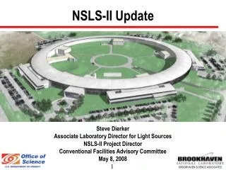
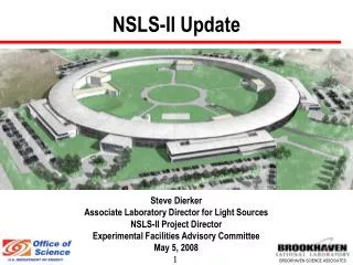
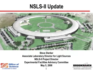
PROJECT OVERVIEW Very broad spectral coverage Far-IR through very hard x-rays Very high brightness > 1021 p/s/0.1%/mm2/mrad2 from ~ 2 keV to ~ 10 keV Very high flux > 5x10¹⁵ ph/s/0.1%bw from ~ 500 eV to ~ 10 keV Very small beam size óy = 2.6 ìm, óx = 28 ìm ó’y = 3.2 ìrad, ó’x = 19 ìrad Top-off operation Current stability better than 1% Design Parameters • • 3 GeV, 500 mA, top-off injection • • Circumference 791.5 m • • 30 cell, Double Bend Achromat • • 15 long straights (9.3 m) • • 15 short straights (6.6 m) • Novel design features: • • damping wigglers • • soft bend magnets • • three pole wigglers • • large gap IR dipoles • Ultra-low emittance • • åx, åy = 0.6, 0.008 nm-rad • • Diffraction limited in vertical at 10 keV • Pulse Length (rms) ~ 15 psec At least 58 beamlines Phase 1 commissioning of Storage Ring Jun 2013 Fully Operation Jun 2015
Alignment Tolerance Storage Ring Error Tolerance Any variation in girder profile falls within the magnet to magnet tolerance budget.
Section 4 Storage Ring Girder, Vacuum Chamber, Magnets Sextupole Magnet Quadrupole Magnet Vacuum Chamber Corrector Magnet Assembly Weight: 8000 Kg Overall Length: 4.8 m Overall Width: .86 m Overall Height: 63” 8 point support system All components are independently adjustable Fiducial mount (1 of 8) Girder Support Plate Grouted to floor
Girder deformation • FEA shows 0.140 mm girder deflection due to gravity without central supports . • Tests show that the girder profile can change as much as ±50 micron or even bigger, mostly in elevation direction, if no alignment efforts are exerted to the girder supports.
Magnet to Magnet Alignment Philosophy • Coarse alignment of magnets and vacuum chamber by laser tracker. • Magnetic alignment by vibrating wire in environmentally controlled room. Record girder profile in the room by laser tracker. • During transportation girder profile will change. In tunnel reproduce girder profile by laser tracker. • Check magnet fiducials to verify magnet alignment.
Instrument Investigated • Electronic autocollimator • HLS • Inclinometer • Laser tracker
Laser Tracker Performance Test in Environmentally Controlled Room • Long term stability test • Dial gage comparison
Vibrating Wire Magnet Alignment in Environmental Room Magnets are magnetically centered on a girder in the environmental room to within ±10 microns in the room using the vibrating wire technique. Environmental room temperature variation < ± 0.10°C. An AC current is passed through a wire stretched axially in the magnet. Magnet centers are determined and magnets adjusted on the girder. Once the centers of magnets are found, magnets are moved to correct positions and bolted down. Paper and talk by A Jain in IWAA 2008.
Magnetic alignment residuals • Vibrating wire system accuracy: ±10 micron • 43 girders included • Magnetic alignment residuals: horizontal ±7 micron vertical ±6 micron
Full Girder Survey A Laser tracker is used to record the final position of the girder fiducials and magnets. This becomes the reference file for the integrated girder. Wire finder is used to correlate the wire center to laser tracker system.
The Measurement Accuracy of Girder Fiducials • Estimated girder profile accuracy : ± 9 micron or better • 12 tracker setup Repeatability test: Max 2 micron.
Installation in Storage Ring Tunnel • A rough survey is performed (200 micron). • Once the ring has been populated, a final precision alignment will be done using laser trackers to place the girder assembly to better than 100 microns of its ideal location. • Before commission the hold down bolts will be tightened to 1000 foot pounds and the girder profile will be reproduced relative to the one in magnetic measurement room.
Girder Profile Reproduction • Measurement Plan (MP) Workflow • Instrument Layout and Observation Plan
Girder Profile Recovery Test • Estimated accuracy: ±9 micron
Girder Transportation Test • June 2009 Girder Prototype Transportation test • Oct 2011 Girder Transportation test • Mar 2012 test (leaking chamber)
Magnetic Center Deviation Check • Check the magnet alignment and make sure no anomalies between magnetic centers • Automated by MP • Center deviation: no bigger than 10 micron
Magnet Alignment Error Estimate • Vibrating wire system error, <±10 micron. • Magnetic alignment residual error, ±6 micron. • Girder profile establishment error in ER, ±9 micron. • Girder profile re-measurement error in tunnel, ±9 micron. • The sphericity and optical centering error of SMR, ±6 micron. • Girder profile reproduction residual error in tunnel, ±10 micron. • According to the law of error propagation, the final magnet alignment error is about ±20 micron. Compared to the ±30 micron tolerance, the expected final error is well under control.
Summary • Laser tracker can achieve ±10 micron accuracy under the circumstance of controlled environment and multiple setup or multiple shooting for all the NSLS-II scenarios. • Girder profiling is an important supplement of vibrating wire technique to maintain the magnet alignment precision. • The estimated magnetic alignment accuracy after vibrating wire and girder profiling step is better than ±30 micron.
Acknowledgements • Thank all the staffs involved in this challenging task. • Thank you for attention!