Download
1 / 27
270 likes | 429 Vues
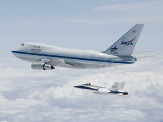
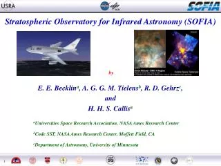
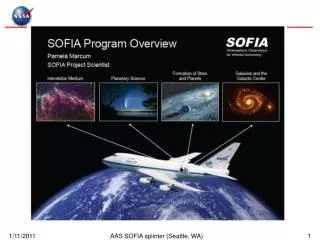
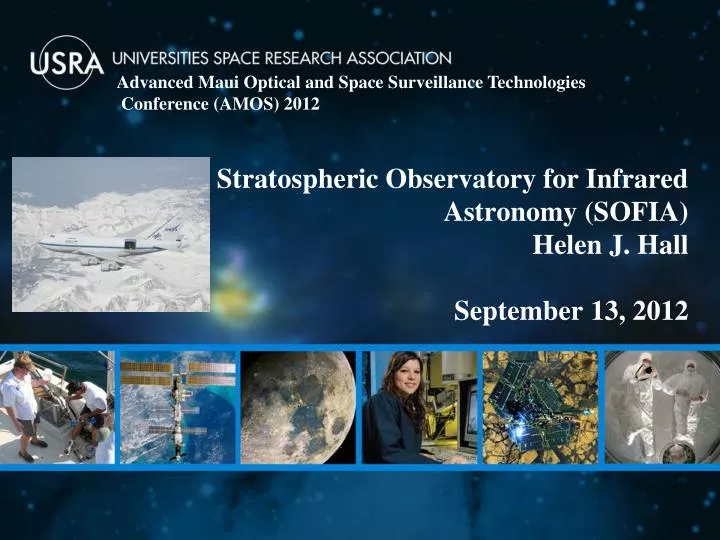
Advanced Maui Optical and Space Surveillance Technologies Conference (AMOS) 2012. Stratospheric Observatory for Infrared Astronomy (SOFIA) Helen J. Hall September 13, 2012. What is SOFIA?. A 2.5 m telescope in a modified B747SP aircraft - Optical-mm performance

E N D
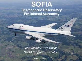
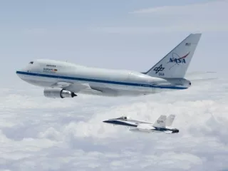
Advanced Maui Optical and Space Surveillance Technologies Conference (AMOS) 2012 Stratospheric Observatory for Infrared Astronomy (SOFIA) Helen J. Hall September 13, 2012
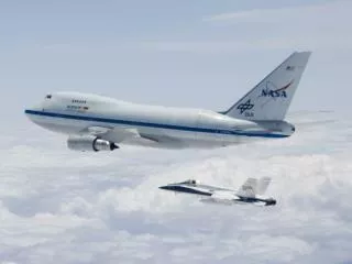
What is SOFIA? A 2.5 m telescope in a modified B747SP aircraft - Optical-mm performance - The obscured Infrared (IR) (30-300 um) is most important Joint Program between the US (NASA - 80%) and Germany ( DLR- 20%) - USRA and the Deutsches SOFIA Institute (DSI, University of Stuttgart) are the science mission contractors Built for 20 year lifetime - Operates at 39,000 to 45,000 feet. - Above > 99% of obscuring water vapor . - Wide instrument range. Future Instrumentalists. World Wide Deployments, will ramp up to ~1000 science hours per year - Science flights to originate from NASA Dryden Flight Research Center (DFRC). - Science Center is located at NASA Ames Research Center.
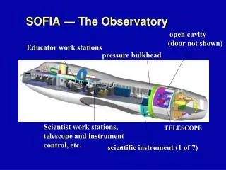
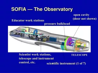
SOFIA — The Observatory open cavity (door not shown) Educators work station pressure bulkhead scientist stations, telescope and instrument control, etc. TELESCOPE scientific instrument (1 of 7)
Basic Roles & Responsibilities Dryden Flight Research Center (DFRC) - Overall Program Management (may be transferred to Ames at full operations). - Aircraft development, testing, operations and maintenance. - Palmdale Regional Airport Operating Location Ames Research Center (ARC) - “Science Project” management USRA and DSI - Science Mission Contractors – Instruments, Observing Time, etc. - Together form a roughly 77 person Science Center at Full Operational Capability - 32 Personnel at Palmdale - 45 Personnel at ARC - DSI is an associate contractor to USRA - USRA relations with DSI are very strong.
The Science Mission Operations has Split Geographic Locations: • SOFIA Science Center at NASA • Ames Research Center • Science Mission Operations Director • & Deputy in place • Science Staff** • Science Data Network (SOFIA • Data Cycle System & Archive) • Mission Planning • Systems Integration Laboratory • Science Instrument • Laboratories • Education & Public Outreach • SOFIA Operations Center at NASA Dryden • Aircraft Operations Facility in Palmdale • Telescope Assembly & Science Instrument • Integration Team • Operations Staff • Early Science Instrument Laboratories • Systems Integration Laboratory • Mirror Coating Facility • Mission Systems Development • (Flight Data & Observatory Data • Cache) **PhD Internships being sponsored between University of Stuttgart and USRA.
Investigator SOFIA Science Center Staff Airborne System Archive Raw Data, House Keeping Data Science Instrument Reduced Data Data Cycle System Tools for Annual Lifecycle Archive & Reduce Data Query & Retrieve Data Science Instrument Integration Science Integration Lab Science Data Products New Science Instruments Raw Data, House Keeping Data Data Manifests Mission Datasets Investigator Execute Observations Joint Observatory Operations Analysis & Prop Support Observatory Maintenance & Operations Observatory Mission Plans Proposal Process Detail Observing Plan Develop Flight Plan Annual Operating Plan Observing Plans Planning Database
Secondary Mirror Infrared Instrument Infrared Light Mirror Visible Light Mirror Visible Light Camera SOFIA Light Path Incoming Infrared Light • Observers in pressurized cabin have ready access to the focal plane Pressure bulkhead Spherical Hydraulic Bearing Light Tube Primary Mirror
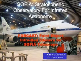
Page 8 Onboard SOFIA –FORCAST mid-IR camera installed
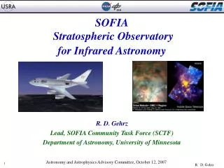
Page 9 Coated Mirror on SOFIA
We are here! Schedule Overview(Tracking Schedule) Instrument Commissioning Inst 1 Inst 2 Backup & Heavy Maint. Inst 3 First In-Flight Light Inst 4 Inst 5 Inst 6 Arrival at Dryden First Door Closed Flight Door open Flight Basic Science TA V&V HIPO Line Ops German FL SS CY07 CY08 CY09 CY10 CY11 CY12 CY13 CY14 CY15 0 1 2 3 Operations ISF ISF FOC FOC Avionics Upgrade (Part 2) Cavity Insulation Segment 3 Downtime Elements Cavity Envir Control Syst ISF = Initiation of Science Flights FOC = Full Operational Capability SS = Short Science Mission Comm Control Syst Observatory Upgrades Science Flight activity Engineering flights A/C Testing/Work
Geographic Distribution of SOFIA Instruments 2013 2010 2011 2011 2011 2014 2015 2015
Instrument R/ graph FIFI LS SOFIA 1st Generation Science Instruments 12
FORCAST – Faint Object infraRed CAmera for SOFIA Facility Instrument Transmission 1 - λ= 5 – 25 µm; 25 – 40 µm [MIR] - FOV: 3.2‘ x 3.2‘ • 0.75“ per pixel - 9 narrow and band filters • Spectral resolution: 5.7 - 250 • Maximum frame rate: 4 per s forfullframe • Highest time resolution: 1.6 mm • Detector: 256x256 Si:As ; Si:Sbblocked 0 λ 5 15 25 35 FORCAST in the lab at Palmdale, CA Simultaneouscontinuumimaging in two MIR bands & Low resolutionspectroscopy PrincipalInvestigator: Dr. Terry Herter,, Cornell University , Ithaca, New York
Image Releases See: Jim DeBuizer Poster this Conference for More detailed Science Results This image was taken with FORCAST and show two regions with the Orion Nebula over a composite photo from Spitzer. The area shown by the red box is known as the Becklin-Neugebauer/Kleinman-Low (BNKL) region of Orion. This region is so bright that it is saturated in the Spitzer image and details cannot be seen. However, in the SOFIA image the region is seen to be composed of many individual young forming stars and knots of dust and gas. (Jim De Buizer) Mid-infrared image of the W3 star forming region from SOFIA/FORCAST, inset on a near-infrared image from Spitzer. The SOFIA image dimensions are 150 x 100 arcseconds, corresponding to 15 x 10 light years at a distance of 6400 light years. Arrow indicates a bubble cleared in the nebula by wind and radiation from the most massive newborn star in the cluster. (SOFIA image, inset: Red, Green, Blue = 37, 20, 7.7 μm; NASA / DLR / USRA / DSI / FORCAST team / F. Salgado, A. Tielens, J. De Buizer) (Spitzer image, background: Red, Green, Blue = 7.9, 4.5, 3.6 μm; NASA / Caltech - JPL).
HIPO – High Speed Imaging Photometer for Occultations Special Purpose Instrument - λ= 0.3-0.6 µm, 0.4 – 1.1 µm [optical/NIR] - FOV: 5.6‘ x 5.6‘ • 0.33“/0.055“ per pixel • Maximum frame rate: 10/20 msforthree 80x80 pixel sub-frames • Through put of HIPOs optic: ≥70 % from 0.4 – 0.9 µm • Detector: e2vCCD47-20 frame transfer silicon CCD • Read out noise: ≤ 6/3 electrons • Quantum Efficiency: 40 – 80 % HIPO in the lab at Palmdale Simultaneoushigh-speed time resolvedimagingphotometryattwooptical/[NIR] wavelength (& FLITECAM >> + NIR) PrincipalInvestigator: Dr. Edward W. Dunham; Lowell Observatory, Flagstaff , Arizona
Occultation by Pluto 2011 June 23 • Dwarf planet Pluto occulted a star • SOFIA met the shadow of Pluto in the mid-Pacific • HIPO and the Fast Diagnostic Camera (FDC) observed the occultation simultaneously Image sequence from the FDC Pluto (circled) is 13 arcsec from the star 200 minutes before the occultation Just before occultation: Pluto and star merged, combined light During occultation: Pluto and star merged, only Pluto light seen After occultation: Pluto and star merged, combined light
FLITECAM – First Light Infrared Test Experiment CAMera Facility Instrument - λ= 1- 5.5 µm [NIR] - FOV: Ø 8‘ • 0.46“ per pixel - Filter: J, H, K, L, L`, M & variousnarrow band filters • Spectralresolution: 1000- 2000 • Maximum frame rate: 4 per s forfullframe • Detector: Raytheon ALADIN II 1024 x 1024 • Read out noise: ≤ 40 electrons • Quantum Efficiency: ~ 80 % • cooled by double liquid helium and nitrogen cyrostat HIPO and FLITECAM co-mounted in the Telescope - Test cameraforimagequality - Simultanoulsymountedwith HIPO (seeabove) PrincipalInvestigator: Ian S. McLean, UCLA Div. Astronomy, Los Angeles, California
GREAT – German REceiver for Astronomy at THz Frequencies - λ= 1.6 – 1.9 THz, 2.4 – 2.7 THz~ 4.7 THz [63 – 187 µm] [FIR] - velocityresolution: ~100 m/s ChannelsAstronomical lines 1.25-1.50 THz[NII], CO, (13)CO, HCN, H2D+ 1.82-1.92 THz[CII], CO 2.4-2.7 THzHD, OH(2P3/2), CO, (13)CO 4.7 THz[OI] - Heterodyne PrincipalInvestigator: Dr. Rolf Güsten, MPI für Radioastronomie, Bonn
FIFI-LS – Far Infrared Field Imaging Line Spectrometer - λ= 42 – 110 µm, 110 – 210 µm [FIR] - FOV: 30“ x 30“; 60“ x 60“ • 6“/12“ per pixel • velocityresolution: 150 – 300 km/s • velocity range 1500 – 3000 km/s • Detector: Ge:Ga • Read out noise: ≤ 40 electrons • Quantum Efficiency: ~ 80 % • opticalsystemcooledto 4 K; detectorcooledto 2 K PrincipalInvestigator: Prof. Dr. Alfred Krabbe, Universität Stuttgart
3D imaging:2D spatially and 1D spectrally Optical slicerplacesthe 2D sky on the 1D spectroscopyslit, so eachobservationcreates an imagecubewithspatialandspectraldimensions.
HAWC: High-resolution Airborne Wideband Camera • λ= 40- 300 µm [FIR/Submm] • - Four Filters at 53, 88, 155 and 215 µm - Bolometer Detector: Goddard Silicon Pop-up Detector (SPUD), 12 x 32 array • Will be upgraded to perform Far Infrared Polarimetry Far Infrared Bolometer Camera PrincipalInvestigator: Dr. Al Harper University of Chicago, Yerkes Observatory, Williams Bay, Wisconsin
λ= 5-28.5 µm [Mid-IR] • Three Modes at 105, 104, and 3000 • Detector: Si:As Blocked Impurity Band (BIB) • Al 6061 (Hyperfine diamond machined) • 4“ x 4“ square, 40“ long grating • Three Spectral Modes: • -R = 50-100,000 cross-dispersed • -R = 15,000 long-slit • -R = 4,000 long-slit • plus source acquisition and pupil imaging camera • Science Drivers: • Proto-planetary disks • H2, H2O, CH4 in emission and absorption • line shapes give spatial distribution in Keplerian disks • Gas in star-formation regions • H2O, CH4, C2H2, HCN, CH3, NH3, HNCO, Fe, Fe+, O+3, Ne+, Ne+4, S, S+2, S+3, Ar+, Ar+2, Ar+4 • Atmospheres of Planets and Satellites High Resolution Echelon Spectrometer EXES: Echelon – Cross – Echelle Spectrograph PrincipalInvestigator: Dr. Matt Richter, University of California Davis, being built at NASA Ames Research Center
SOFIA EP/O • Airborne Astronomy Ambassadors (AAA) Program Launched • All 6 US educators in the first AAA class flew on Basic Science 1 flights • Parallel German AAA program flew their first educators during Basic Science 2 Educators from the first Airborne Astronomy Ambassadors flight. (l-r) Margaret Piper, Lincoln Way High School, Frankfort, Ill.; Theresa Paulsen, Mellen School District, Mellen, Wis.; and Kathleen Joanne Fredette, Desert Willow Intermediate School, Palmdale, Calif.
Program making progress! • Early Science with FORCAST and GTREAT was a great success. (31 refereed papers published) • Aircraft upgrades in the works • Next General Observing Cycle starts November 2012 • SOFIA will be one of the primary facilities for far-IR and sub-millimeter astronomy for many years
Red = 37.1um,Green = 24.2um,Blue = 5.4um SOFIA First Light Image, May 25, 2010