Download
1 / 57
720 likes | 1.31k Vues
Advances in Avalanche Photodiodes. Y. Musienko * Northeastern University, Boston & CMS ECAL collaboration. * On leave from INR(Moscow). Avalanche multiplication APD’s for supercollider - requirements Different APD structures APDs for the CMS ECAL Radiation hardness and reliability

E N D
Advances in Avalanche Photodiodes Y. Musienko* Northeastern University, Boston & CMS ECAL collaboration *On leave from INR(Moscow)
Avalanche multiplication APD’s for supercollider - requirements Different APD structures APDs for the CMS ECAL Radiation hardness and reliability APDs at low temperatures New APD developments Conclusion Outline Advances in APD's Y.Musienko
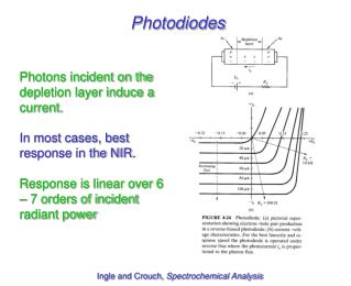
Avalanche multiplication Avalanche photodiodes are photodiodes with built-in high electric field region. With increasing reverse bias voltage, electrons (or holes) are accelerated and can create additional electron-hole pairs through impact ionization. Silicon is a good material for APD construction: high sensitivity in visible and UV range, significant difference between ionization coefficients for electrons and holes – smaller positive feedback and smaller multiplication noise Excess Noise Factor: F=k*M+(1-k)(2-1/M) k=b/a (k-factor) b- ionization coefficient for holes a- ionization coefficient for electrons (see R.J. McIntyre, IEEE Tr. ED-13 (1972) 164) Ionization coefficients as a function of electric field in silicon Advances in APD's Y.Musienko
APDs are used in telecommunications > 30 years To be used in HEP they should satisfy certain requirements Requirements depend on the application Applications: Calorimetry SciFi trackers Cherenkov light detection TOF … APD’s for supercolliders Here I will discuss mainly the applications of the APDs for HEP calorimetry CMS ECAL is a good example Advances in APD's Y.Musienko
3 Density [g/cm ] 8.28 8.9 Rad length, [mm] X 0 Interaction length [mm] 224 Molière radius [mm] 21.9 Decay time [ns] 5 (39%) 15 (60%) 100 (1%) Refractive index 2.30 Max emission [nm] 425 Light yield [photon/MeV] ~50 Temp coeff [%/ºC] -2 Lead Tungstate Properties • Advantages: • Fast • Dense • Radiation hard • Emission in visible • Disadvantages: • Temperature dependence • Low light yield Advances in APD's Y.Musienko
In the CMS ECAL : - high radiation levels - 4T magnetic field - limited space - PbWO4 (low light yield, 420-450 nm emission peak) Photodetector must be : - radiation hard - operational in high magnetic field - small nuclear counter effect and reasonable gain - small excess noise factor - match the properties of PbWO4 light (high QE, high speed) - low sensitivity of the gain on temperature and voltage - high reliability (10 years of LHC) and low price !!! PIN photodiode has no gain and has high “nuclear counter effect” Avalanche Photo Diode APDs from several producers had been considered Photo Detector Requirements Advances in APD's Y.Musienko
“Beveled edge” APD (API) It is made by growing the p-type epitaxial layer on n-type neutron transmutation doped silicon. The broad gain region enables device operation at high gain with low excess noise and excellent gain uniformity. The APD edge (perpendicular to the junction) is beveled in order to reduce the field along the device edge, enabling the device to sustain the high biases necessary for APD operation. Schematic cross-section and electric field profile, according to Advanced Photonix Inc. (from M.Moszynski et al., NIM A485 (2002) 504) Advances in APD's Y.Musienko
Deep-diffused “beveled edge” APD (RMD) Gain ~104 possible Low energy gamma detection (~200eV threshold) R. Farrell et al., NIM A353 (1994) 176 Advances in APD's Y.Musienko
API APDs (Gain and QE) • High gain >100 • Large area – up to 16 mm in diameter • High QE • Low excess noise factor (measured by Advanced Photonix, Inc.) Advances in APD's Y.Musienko
API APD – Scintillation Light Detection Pulse height spectrum of scintillation due to 5.5 MeV a-particles in liquid Xe (l=178 nm), measured at T=-102 C and M=120 (V.N. Solovov et al., NIM A488 (2002) 572) Energy spectrum of 662 keV g-rays measured with CsI(Tl) and YAP:Ce crystals (M. Moszynski et al., NIM A497 (2003) 226) Advances in APD's Y.Musienko
“Beveled edge” APDs in HEP environment When operating these APDs at high gain in beam line environment, abnormal behavior and eventually permanent damage to the detectors were observed. These abnormal events were probably triggered by rare but highly ionizing nuclear collision events Pulse height spectra of APD response to a-particles at different bias voltages: U=1000 V, M=1.2 U=1500 V, M=2 U=1650 V, M=4 U=1700 V, M=5 U=1750 V, M=6 APD leakage current vs. bias voltage before and after lethal a-particles damage (From G. Anzivino et al., NIM A430 (1999) 100) Advances in APD's Y.Musienko
Excellent photosensor: Large area High QE and gain Good uniformity over the sensitive area Low excess noise factor Low voltage and temperature sensitivity But: High operating voltage (~2000 V) High sensitivity to heavily ionizing particles Structure should be sensitive to hadron irradiation Difficult for mass production High price “Beveled edge” APD’s summary Advances in APD's Y.Musienko
“Reach-through” APD Schematic cross-section and electric field profile Structure optimized for red light detection, (see for example: I. Wegrzecka, M. Wegrzecki, NIM A426 (1999) 212) Structure with improved sensitivity for blue light (see for example R. Lecomte et al., NIM A278 (1989) 585 • Guard-ring - to reduce electric field at the edge • Region with high electric field is thinner than in the case of beveled edge APDs • Region with low doping - to reduce capacitance and operating voltage (<500 V) Low operating voltage, easy to produce - good for mass production,but high signal from ionizing particles crossing the APD depletion region (“nuclear counter effect”) and high dark current induced by hadron irradiation (thick depletion region) Advances in APD's Y.Musienko
“Reverse” or “Baried Junction” APD (EG&G) Standard or “rich-through” APD “Reverse” or “baried junction” APD The peak field is ~4 mm deep R. Lecomte et al., NIM A423 (1999) 92 Advances in APD's Y.Musienko
“Reverse” APD performance Area: 5x5 mm2 Capacitance: ~30 pF (for 120 mm depletion region) Excess noise factor (M=50): 3.5 R. Lecomte et al., NIM A423 (1999) 92 Advances in APD's Y.Musienko
Doping profile and electric field distribution (calculated) Y. Musienko et al., NIM A442 (2000) 179 APD is made on 120 mm thick high resistivity wafer. For mass production 200 or even 300 mm thick wafer is preferable (lower production cost and better yield) Advances in APD's Y.Musienko
Thick APDs under neutron irradiation Calculated Calculated and measured Neutrons cause the change of the doping profile, electric field distribution and shift the gain curve. Effect is proportional to the square of the depletion region thickness APDs with depletion region of ~40-60 mm are optimal Y. Musienko et al., NIM A442 (2000) 179 Advances in APD's Y.Musienko
“High C” Hamamatsu APD Sensitive area 19.6 mm2 Operating voltage ~150 V Excess noise factor 2.0 1/M*dM/dT -2 %/C Effective thickness ~4 mm QE(430nm) 60 % Capacitance 320 pF 1/M*dM/dV 15 %/V Produced by epitaxial growth, ion implantation and diffusion – easy to produce Advances in APD's Y.Musienko
In 1995 there was no APD which was suitable for CMS ECAL Main goal of R&D – optimize APD structure for the CMS ECAL 1995 - Development contract with Hamamatsu Photonics and EG&G Opto-electronics, they had APDs which were close to the CMS ECAL requirements Hamamatsu: small NCE (~4mm), small F, small temperature sensitivity of the gain high capcitance (320pF for 5 mm in dia. APD), 15%/V change of the gain (when M~50) Goals of R&D: - reduce capacitance - reduce voltage sensitivity of the gain EG&G: small capacitance (~30pF for 5x5 mm2 area), small voltage sensitivity of the gain ~1.5%/V high F (3.5 for M~50), high temperature sensitivity of the gain Goals of R&D: - reduce F - reduce temperature sensitivity of the gain Contradiction:low nuclear counter effect high capacitance, high voltage sensitivity of the gain 3 years of exciting (!!!) work on CMS ECAL APD development… Choice between the two vendors made in July 1998 in favour of Hamamatsu Photonics (both producers produced good APDs, but Hamamatsu had better reliability and smaller price) New R&D contract with Hamamatsu: - reduce capacitance from 120 to 80 pF, larger VB-VR, improve resistance to radiation (~100% survival!) … 2 more years of R&D … R&D on APD for CMS ECAL Advances in APD's Y.Musienko
Hamamatsu APD structure (final CMS APD) Photo-electrons from THIN p-layer induce avalanche at p-n junction Electrons from ionizing particles traversing the bulk amplified with relatively small gain (Me=50, Mh=1.5) 2 APDs (each 5 x 5 mm) mounted in a capsule ready for gluing to a crystal Advances in APD's Y.Musienko
APD’s in the CMS detector Electromagnetic Calorimter PbWO4 crystal 61200 Crystals in Barrel 2 APDs per Crystal Advances in APD's Y.Musienko
Resolution: where,a :due to intrinsic shower fluctuations b: related to stability and reproducibility c: noise contributions CMS design goal :a ~3%, b~0.5%, c~200 MeV APD contributions: a- photon statistics (area, QE) & excess noise factor b- gain variation with bias voltage and temperature c - capacitance as series noise and dark current as parallel noise Optimise all these parameters to reach design goal APD Impact on ECAL Resolution Advances in APD's Y.Musienko
Nuclear Counter Effect 80 GeV electrons in PbWO4 PIN diode or APD readout Tail due to particles leaking through crystal and traversing diode PIN diode APD No tail ! APD effective thickness for traversing particles: ~6 μm Advances in APD's Y.Musienko
APDs in the magnetic field (7.9 T) APD gain curve measured outside the field J.Marler et al., NIM A449 (2000) 311 APD surface oriented perpendicular to the field APD surface oriented parallel to the field Gain of APD is unaffected by the 7.9 T magnetic field Advances in APD's Y.Musienko
APD Gain, Quantum efficiency PbWO4peak emission 420 nm Operating Voltage, M=50 Gains can go to over 1000 We demand good behavior up to gain 400 Q.E. is ~73% at peak emission Advances in APD's Y.Musienko
Voltage and Temperature Coefficients At M=50 : dM/dV*1/M = 3.1 %/V dM/dT*1/M = -2.4 %/C Advances in APD's Y.Musienko
Gain vs. Wavelength Main junction is close to the entrance window – red light has smaller gain Advances in APD's Y.Musienko
statistical fluctuations of the avalanche multiplication F = k×M + (2-1/M)×(1-k) (from theory of R. McIntyre) k - ratio of the ionisation coefficients for holes and electrons, M- gain Contributes to the stochastic term in energy resolution as: SQRT(F/Np.e.) Excess Noise Factor Advances in APD's Y.Musienko
Summary of APD parameters (M=50) Active area5 x 5 mm Operating voltage (T=25C)< 420 V Quantum Efficiency (420 nm)73 % Capacitance 80 pF Serial resistance < 10 Ω Dark Current (t=25 C)~3.5 nA Voltage sensitivity (1/M*dM/dV)3.1 % / V Temperature sensitivity (1/T*dM/dT)- 2.4 % / C Excess noise factor2.1 Breakdown - operating voltage (Vb - Vr)45 ± 5 V For GOOD APDs: RADIATION HARDNESS: After 10 years of LHC equivalent hadron irradiation, ONLY property to change is thedark current,which rises to~5 μA at 18C AGING: No effect seen after ~10 years’ equivalent in an oven. Advances in APD's Y.Musienko
Test beam: Energy Resolution Reconstructed energy with 280 GeV electrons incident on 5x5 crystal matrix Advances in APD's Y.Musienko
Radiation doses are in red, 104 Gy. Neutron fluence is in green, 1013 neutrons/cm 2 with E > 100 keV. Radiation level after 10 years Crystal calorimeter 100 Advances in APD's Y.Musienko
APD’s irradiated at PSI 70 MeV proton beam for 105 minutes 9x10¹² protons/cm2 2x10¹³ 1MeV neutrons/ cm2 10 years fluence expected in CMS barrel Irradiation with 70 MeV protons Advances in APD's Y.Musienko
Neutron irradiation results To date >1000 APD’s have been irradiated by 252Cf neutrons and all have survived Advances in APD's Y.Musienko
Effect of Irradiation on Q.E. No change in quantum efficiency for ’s of interest Very small change of gain curve and APD breakdown voltage up to 1014 n/cm2 Advances in APD's Y.Musienko
Dark Current & Noise After 2*1013 n/cm2 and annealing Id~5A @ 18 oC ENC~12 500 el (t = 50 ns) 50 MeV/ch Advances in APD's Y.Musienko
Good APDs are very Robust, Radiation Hard They still work after more rigorous tests (some “violent”) BUT Despite heroic effort by Hamamatsu - few % die or get sick under gamma irradiation - a few more in an extended “burn-in” at 80 C Reliability goal 99.9%, for 10 years of LHC ==> Screen all APDs Radiation Hardness, Stability Advances in APD's Y.Musienko
Change of VB after irradiation and annealing Rejected APD’s Advances in APD's Y.Musienko
Dark Current and Noise APD with a significant shift of Vb after 60Co irradiation shows abnormal behavior of Id/Gain curve and high noise Id/Gain Noise Advances in APD's Y.Musienko
APDs Screening Procedure 60Co, 5 kGy, isotropic (2 hrs) Cylinder 32 60Co wires Cook at 80 C for 4 weeks under bias CERN PSI Measure Vb, Id Measure Vb, Id 1 day later; Noise > 1 week Select, pair Make Capsule Measure Noise Lyon Advances in APD's Y.Musienko
APDs are rejected if after irradiation or cooking: Change of Vb(breakdown voltage) :> 5 V Id (dark current):anomalously large Id/M (Id divided by gain, M):rises in range M = 50 - 400 Noise:anomalously large at M = 1, 50, 150, 300 Also: Bad Positions: All APDs in a Lot from a position on wafer where > 30% fail screening Rejection Criteria Advances in APD's Y.Musienko
Efficiency of the screening method 834 APD`s which passed 1st irradiation and annealing were irradiated the 2nd time. Only 1 APD failed the second irradiation. Advances in APD's Y.Musienko
Production Status (to end 8/03) 115,000 delivered On schedule to complete by January 2004 (140,000 APDs) 90,000 screened On schedule to complete by May 2004 Advances in APD's Y.Musienko
The Hamamatsu APD for CMS - is very robust - is radiation “hard” - will have Id after 10 years of LHC ~ 50 MeV noise per crystal By screening out ca 5% of APDs, anticipate 99.9% reliability in CMS Production and screeningon schedule Summary on CMS APD’s Advances in APD's Y.Musienko
Planar APDs from RMD This APD is really large! 64-pixel APD array 0.9x0.9 mm2 pixel size Advances in APD's Y.Musienko
Avalanche photodiodes: Arrays S8550 4x8 pixel array, 1.6x1.6 mm2 pixel size, 2.3 mm element pitch, low noise and enhanced UV sensitivity 2.1x2.1mm2 pixel size Arrays of APDs can be produced with a very good fill factor. The biggest problem is the connection to the readout electronics. 16 CsI(Tl) crystal coupled to the array and illuminated by a 22Na source R. Farrell et al., NIM A442 (2000) 171 Advances in APD's Y.Musienko
Position Sensitive APDs (RMD) (From talk given by K.S. Shah at “New developments in photodetection”, Beaune, 2002) Advances in APD's Y.Musienko
Quantum efficiency and spatial resolution (14x14 mm2 APD, 25 C) (From talk given by K.S. Shah at “New developments in photodetection”, Beaune, 2002) Advances in APD's Y.Musienko
Photon counting at low temperatures Hamamatsu 5x5 mm2 APD successfully operated at T=100K. For 470 nm light ~16 % photon detection efficiency was measured with an APD operated at M~8000 and 2550 el. electronics threshold, while noise count was extremely low (0.1 Hz) A. Dorokhov et al., NIM A504 (2003) 58 Advances in APD's Y.Musienko
APD’s operated in Geiger mode • Single pixel Geiger mode APD’s developed long time ago ( see for example: R.Haitz et al, J.Appl.Phys. (1963-1965)) • Commercially available from single producer: Perkin Elmer Optoelectronics (up to Ø500 mm active size) A prototype of sci. fiber hodoscope (Ø1mm fibers) was built and efficiencies up to 90% for 20 GeV electrons were reached.High sensitivity to radiation damage by neutrons was found (W. Bruckner et al., NIM A313 (1992) 429) • Single pixel devices are not capable of operating in multi-photon mode • Sensitive area is limited by dark count and dead time (few mm2 Geiger mode APD can operate only at low temperature, needs “active quenching”) Solution: multipixel Geiger mode APD Advances in APD's Y.Musienko