Download
1 / 23
230 likes | 408 Vues
CLIC drive beam injector design. S. Bettoni, R. Corsini, A. Vivoli (CERN). Outline. CTF3 drive beam injector: Design, experimental verifications CLIC drive beam injector layout: Optimization process and criteria Proposed layout Longitudinal and transverse beam dynamics simulations

E N D
CLIC drive beam injector design S. Bettoni, R. Corsini, A. Vivoli (CERN)
Outline • CTF3 drive beam injector: • Design, experimental verifications • CLIC drive beam injector layout: • Optimization process and criteria • Proposed layout • Longitudinal and transverse beam dynamics simulations • Critical view of the results and possible cures • Conclusions & outlook
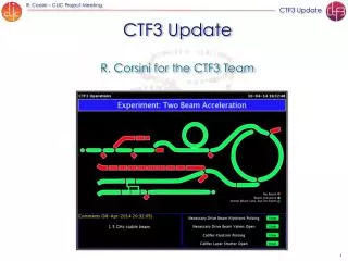
Drive beam injector: CTF3 example even buckets odd buckets • RF deflector n0 / 2 Gap creation and combination Phase coding Sub-harmonic bunching n0 / 2 180 phase switch Acceleration n0 Deflection n0 / 2
Drive beam injector: CTF3 experience Key parameters for the SHB system: • Time for phase switch < 10 ns • Satellites (particles captured in 3 GHz RF buckets) population < 7 % Satellite bunch population: Phase switch: Main Satellites Phase switch within eight 1.5 GHz periods (<6 ns). Satellites bunch population estimated to ~8 %.
CTF3 first rescaling: the SHB system • Lshb = 3*LshbCTF3 (6 cells) • Gshb = GshbCTF3/3 CTF3 • Lshb = 2/3*LshbCTF3 (4 cells) • Gshb = 3/4*GshbCTF3 • Lshb = LshbCTF3 (2 cells) • Gshb = GshbCTF3
The Matlab driven optimization tool Starting distribution Parmela file input Parmela run Automatic minimization process Analysis of the results
The optimization process: some details • During the optimization: • The code varies the parameters of the system and it does some checks on them • From the output of Parmela the tool calculates the number of particles in the main of the reference particles cutting the distribution at the target bunch length • The number of particles in this region is maximized
CLIC drive beam injector layout Solenoids Thermionic gun Buncher SHB Prebuncher Accelerating cavity 140 KeV 6 MeV Slit 26 MeV 53 MeV Quadrupole Bend
Exit of the gun Energy = 0.140 MeV sE= 0.00016 MeV DT= 6 ns gbex,y= 3.48 mm rad
SHB system Energy = 0.138 MeV sE= 0.029 MeV DT= 9.68 ns
Prebuncher Energy = 0.147 MeV sE= 0.035 MeV DT= 9.7 ns Satellites= 5.5 %
Buncher Energy = 4.20 MeV; sE= 1.01 MeV; st= 55.89 ps.
Exit of the solenoids (E30 MeV) Energy = 26.34 MeV; sE= 2.16 MeV; st= 36.58 ps.
Cleaning chicane R5,6 = 78 mm CTF3 Before the chicane After the chicane Bend length = 15 cm; Bend angle = 14.32 deg; Reference E = 26 MeV; Slit aperture = 7 mm; Intensity decrease = 24%.
After the cleaning chicane Before the chicane After the chicane Energy = 26.07 MeV; sE= 0.40 MeV; st= 17.14 ps.
Injector exit (E50 MeV) Energy = 53.25 MeV; sE= 0.45 MeV; st= 9.45 ps. gbex= 32.92 mm rad; gbey= 28.73 mm rad.
CLIC drive beam injector design: a critical view • More optimizations still ongoing: • Intensity decrease at the chicane = 24% (close to CTF3 20%) • Additional chicane needed • (power???) • Satellites population = 4.9 %
Satellites minimization: possible cures • Identified two approaches to minimize the satellites content: • Minimize the number of particles in the time interval of the satellites • Use an additional SHB to shift the energy of the satellites CDR version Modified version Starting from an idea by P. Urschütz (presently at Siemens)
Efficiency: an alternative solution • Re-optimization using as a figure of merit the energy spread at a fixed bunch length and optimization of the accelerating cavities: • Intensity decrease at the chicane = 19% (24%) • Total losses from the start = 22% (30%) • Particles to be lost in the additional chicane reduced by a factor 2 Particles in a more confined E-t region
Conclusions A design of the CLIC drive beam injector based on a thermionic gun has been studied Parmela simulations verified that the challenging CLIC requests can be fulfilled (longitudinal & transverse) Identified some possible improvements (beam losses, satellites content) and optimization already ongoing Further studies (beam loading compensation, wakefields effects and beam stability) to be done Proper RF design of the elements to be done
Spare slide: space charge Without space charge With space charge