Download
1 / 55
550 likes | 575 Vues
S. Bettoni for the CTF3 commissioning team. CTF3 commissioning status. Outline. CTF3 for CLIC Machine commissioning : Combiner ring model improvement New lines in operation: TL2 TBTS CALIFES 2008 milestones: Factor 4 recombination demonstrated

E N D
S. Bettoni for the CTF3 commissioning team CTF3 commissioning status CTF3 commissioning status
Outline • CTF3 for CLIC • Machine commissioning: • Combiner ring model improvement • New lines in operation: • TL2 • TBTS • CALIFES • 2008 milestones: • Factor 4 recombination demonstrated • First drive beam in PETS (w/o and w recirculation) • First probe beam • Bunch length measurement: • RF pickup • Coherent diffraction • Other topics: • Steering algorithms • Transient compensation • The 2009 of CTF3 • Conclusions
Drive beam - 100 A, 240 ns from 2.4 GeV to 240 MeV 140 MW Main beam – 1 A, 160 ns from 9 GeV to 1.5 TeV CLIC as a multiTeV collider Basic features • High acceleration gradient (100 MV/m) • “Compact” collider - overall length @ 3 TeV 50 km • Normal conducting accelerating structures • High acceleration frequency (12 GHz) • Two-Beam Acceleration Scheme • Cost effective, reliable, efficient • Simple tunnel, no active elements • Modular, easy energy upgrade in stages
326 klystrons33 MW, 139 ms combiner rings Circumferences delay loop 72.4 mCR1 144.8 mCR2 434.3 m drive beam accelerator2.38 GeV, 1.0 GHz CR1 CR1 1 km Delayloop CR2 CLIC Layout 3 TeV 326klystr 33MW drive beam accelerator2.38 GeV, 1.0 GHz 1 km 4.2A, 139 ms Delayloop CR2 decelerator, 24 sectors of 878 m Drive beam generation complex BDS2.75 km BDS2.75 km 101A, 244ns BC2 BC2 245m 245m IP e+ main linac e- main linac , 12 GHz, 100 MV/m, 21.1 km TAR=120m TAR=120m 48.4 km Main beam booster linac, 9 GeV Main beam generation complex BC1 e+ injector, 2.4 GeV e- injector2.4 GeV e-PDR365m e-DR365m e+PDR365m e+DR365m
structures 12 GHz PETS on-off deceleration stability two-beam acceleration structures 30 GHz CTF3:CLIC R&D Issues – WHERE? • Small scale version of the CLIC RF power source • Provide the RF power to test the CLIC accelerating structures and components • Full beam-loading accelerator operation • Electron beam pulse compression and frequency multiplication • Safe and stable beam deceleration and power extraction • High power two beam acceleration scheme recombination x 4 recombination x 2 bunch length control bunch compression fully loaded acceleration phase-coding Structures Structure materials Drive Beam generation PETS on-off DB decelerator CLIC sub-unit
F D F F D D F F D D F F F F D D F F F F F F D D F D D D D D F F D D D D F F D D F F D D F F D D D F F D D D D F D D F D F CTF3 status in the years 2004 2005 Thermionic gun Linac DL CR 2006/7/8 F F D D D D F F F F D D F F D D F F F F D D F F F F F F D D F F D D D D D D F F D D D D F F D D F F D D D D F F F F D D D D D D F F F F D D D D D D D D F F D D D D F F D D F F CLEX CTF2 CLEX2007-2009 building in 2006/7 30 GHz production (PETS line) and test stand Photo injector / laser tests from Oct. 2008 TL2 2008 TL2, TL2’ installed Complete apart from TBL
Main points of the commissioning • Delay loop: • 2 x current multiplication by DL • TL1: • 3.5 A in TL1 • Magnetic and RF injection in CR • CR: • Bad cabling quadrupoles • Wrong BPM calibration • Combined function magnets not properly modeled • FAST VERTICAL INSTABILITY
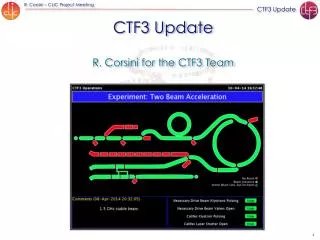
The 2008 of CTF3 30 GHz 30GHz only DL & CR RUN 1 DL, CR, TL2 TBTS Installation:TL2, CALIFES, TBTS Today Linac only RUN 2 Linac, Ring area, (CLEX) PETS in TBTS Installations CALIFES PETS CALIFES RUN 3
2008 CTF3 experimental program • 1st run (April - June) • Injector & Linac: establish stable & documented working point, automatic beam steering & steering algorithm studies, diagnostics consolidation, stability studies, EUROTeV BPMs • Delay Loop: complete beam optics measurements (dispersion, orbit, kick measurements, matching), re-establish combination • TL1 & combiner ring: complete optics studies (dispersion, closed orbit correction, matching, tunes, kick measurements, quad displacement evaluation, matching), tune and b function dependence of vertical instability, factor four combination with DL bypass (≥ 10 A) • DL, TL1 & CR: factor 8 combination (≥ 15 A) • 2nd run (July - September) • Complete DL + CR, new RF deflectors (20 A ?) • TL2 commissioning • First CALIFES commissioning • TBTS commissioning (no PETS) • 3rd run (September - December) • Complete above program • Coherent Diffraction Radiation tests • TBTS, PETS running in
2008 CTF3 experimental program • 1st run (April - June) • Injector & Linac: establish stable & documented working point, automatic beam steering & steering algorithm studies, diagnostics consolidation, stability studies, EUROTeV BPMs • Delay Loop: complete beam optics measurements (dispersion, orbit, kick measurements, matching), re-establish combination • TL1 & combiner ring: complete optics studies (dispersion, closed orbit correction, matching, tunes, kick measurements, quad displacement evaluation), tune and b function dependence of vertical instability, factor four combination with DL bypass (≥ 10 A) • DL, TL1 & CR: factor 8 combination (≥ 15 A) • 2nd run (July - September) • New RF deflectors, Complete DL + CR (20 A ?) • TL2 commissioning • First CALIFES commissioning • TBTS commissioning (no PETS) • 3rd run (September October - December) • Complete above program First CALIFES commissioning • Coherent Diffraction Radiation tests • TBTS, PETS running in
Measurements in CTF3 • Several measurements are performed in the machine to validate the optics models: • Response matrix: • High precision method • Symmetric and multiturn kick (ring) • Dispersion measurements • Tune measurements • Steering algorithms applied in the machine: • Ring orbit correction • Dispersion free steering (Linac) • Bunch length measurement • Transient compensation
Gun instability Unstable Stable CTF3 Linac is fully loaded The energy transferred to the beam depends on the beam current • The current is different shot to shot • The energy gain is different shot to shot • Position jitter in dispersive regions • Set up and measurements VERY difficult Gun instability (HV fluctuations) Problem solved since September 2008
Combiner ring CTF3 commissioning status
Combiner ring kick measurements • To maximize the precision of the measurement in the ring: • The multiturn response matrix has been measured: easier to identify the discrepancies • Symmetric kicks analysis: easier to identify a single quad error • Several bugs found TURN 1 TURN 2 TURN 3
Combiner ring: correcting the bugs Dispersion • Combined function magnets (reused from EPA): • New model of the combined magnets has been used • The k1 strength has been lowered with respect to the one used in the EPA model • Increase of the strength of the J-type quads • Cross-cabled control units for quadrupoles power converter Tunes
Tune measurements W/O correction Wiggler currents adjusted according to kick measurements W correction
Fast vertical instability disappeared! current vertical horizontal Old deflectors BPM signals shoving vertical instability New deflectors BPM signals, no instability
Transfer line TL2 large part done by RRCAT: Optics design Aluminium vacuum chambers Bending magnets CTF3 commissioning status
TL2 optics • Module-3 • Tunable R56 (from -0.35 to +0.35) • Achromatic arc • Final matching doublet • Module-2 • Straight section for tail clipper • CLEX-CR buildings not at the same height (achromat) • Matching section • Module-1 • From CR extraction point to the first bend magnet (achromat) Beam direction For more details see “Optics design”, Amalendu Sharma et al., 2007 CTF3 collaboration meeting, Link
Beam setup in TL2 MTV TL1 LINAC CT DL CR CTS TL2 CLEX → Quad scan in CTS and tracking to the start of TL2 → Uncertainty on the initial conditions: → Error in the TL1/CR model → Small variations of the quads strength in the TL1/CR model → Error in the measurement propagated through TL1 and CR → New equipment to read the BP in the line: → Some problems at the beginning of the commissioning → Relatively strong optics → Since a certain time radiation alarm made operation in this area slow and annoying
Beam through TL2 → Uncertainty on the initial conditions: → Modified module-2 quads to compensate the possible different initial conditions → Found and corrected model-measurements discrepancies in CR (only during this shut down) → Installed MTV at the beginning of TL2 (during this shut down) → Greatly improved the BPs reading (interactions with LAPP people) → Relaxed optics searched →Discovered bug: → last quadrupole of the first triplet of module-2 had a maximum value lower than the read one (Loic) TL2 status at the end of the year BUT …
Kick measurements Kick 615 Kick 435 Kick 125 → Up to now NO huge discrepancies between the machine and the model found
CRM TL1 DL CR TL2 CLEX For 2009 run improvements The operation of the machine was very tedious in the CR extraction zone because of radiation problems. • During this shut-down the two exit chicanes were extended • Tail Clipper installed in TL2: • It is made of kicker and dump that sits just above the beam • It allows to regulate recombined train length • The dump serves as a beam stopper to protect CLEX so It makes possible simultaneous operation of DL/CR and installations in CLEX
F D F F D D F F D D F F F F D D F D F F D D F F D D F F D D F F D D D D F F D D F F D F D F D D F D F D D F D D F D D F D F D F TBL TBL 6 m F F F D D D D D F F DUMP DUMP F F F F D D D D F F F F D D D D F F F F F F F F D D D D F F F F F F F F F F F F D D D D F F F D D D D D D D D D D D F F F F D D D D D D D D F F F F TL2 TL2 ’ ’ D D D D 1.85m 1.85m 1.85m DUMP DUMP F F F F 2 D D D D D D F F F F F F D D D D D D D D D F F F F F F D D D DUMP DUMP 0.75 0.75 m D D D D D D D D D F F F D D D F F F D D D D D D F F F LIL LIL LIL - - - ACS ACS ACS LIL LIL LIL - - - ACS ACS ACS LIL LIL LIL - - - ACS ACS ACS 8 m 8 m 8 m 16.5 m DUMP DUMP F 22 m TBTS TBTS CALIFES Probe beam injector CALIFES Probe beam D 2.5m 2.0m 2.0m 2.0m F 16 m ITB DUMP DUMP ITB (not base-line) 42.5 m 42.5 m 42.5 m CLEX (CLIC Experimental area) existing building F F D D D D F F F F D D F F D D F F F F D D F F D D F F D D F F D D F F D D F F D D D D F F D D F F D D F F D D F F D D D D F F D D F F D D D D F F D D D D F F D D D D F F D D Test Beam Line TBL Two Beam Test Stand Probe Beam Everything installed, apart from TBL CTF3 commissioning status
PETS A fundamental element of the CLIC concept is two-beam acceleration, where RF power is extracted from a high-current and low-energy beam in order to accelerate the low-current main beam to high energy.
Drive beam generation scenarios CTF3 #1 DL DBA CR CTF2 TBTS <30A CLEX CTF3 #2 DL CR 14 A CTF2 TBTS CLEX CTF3 #3 To produce the CLIC nominal PETS power 22 A drive beam would be necessary. DL CR 4 A CTF2 TBTS CLEX
To the Load Variable Splitter (coupling: 01) Variable phase shifter PETS output PETS input Drive beam The recirculation PETS with external re-circulation A fraction of the power going out from PETS is resent to the SAME PETS structure CLIC nominal 6.0 A Problem 2008 run: Splitter: stuck in undefined position (not remotely controllable) Phase-shifter: stuck in undefined position (not remotely controllable) 5.0 A 4.0 A 3.5 A 240 ns CLIC nominal R. Corsini, I. Syratchev
Beam in TBTS PETS story Total ~ 30 hours integrated conditioning time (15/11/2008 to 15/12/2008) Gradually increasing current arriving at PETS, up to ~ 5A, 11/12 14/11: First beam 2A w/ recirculation (by chance: positive build-up!) 21/11: Manually forces splitter to extreme position: no recirculation (to verify beam generated RF power) 28/11 : Adjusted phase-shifter : back to constructive recirculation mode
The recirculation: measurements With the maximum current sent to PETS (~5 A) this year 30 MW power obtained instead of less than 5 MW! Power: PETS out, to load, reflected Corresponding pulse intensity^2 (the BPM before, and two first after PETS): E. Adli, R. Corsini, I. Syratchev
The recirculation: model/measurements Model (power) Measured (power) Measured (current) Very nice according of the modeling with the measurements E. Adli
1.85m D D D D D D D D D D F F F F F F F D D F F F D D D F F F F F F F F F D D D D D D D D LIL-ACS LIL-ACS LIL-ACS CALIFES commissioning • Dec 1st • Earlier the laser was used by PHIN • The beam with laser pulse train of 100 ns length (150 bunches) • 100% transmission through the 1st cavity • Dec 8th • Laser broken • Measurements continued using the dark current • 30th March • Restart TBL DUMP D F TL2’ DUMP TBTS DUMP DUMP CALIFES Probe beam injector
Steering algorithms Several steering algorithms have bee applied in the machine → Closed orbit correction (ring) → Dispersion free steering (Linac)
CR orbit correction algorithm Best eps value iteratively determined: →Tolerance on the maximum allowed beam displacement and maximum value of the currents in the correctors for i = 1:n_max_step if i == 1 eps(i) = eps_start*fact; else eps(i) = eps(i-1)*fact; end [theta_s,thetap_s,corr_s,final_s,idec_s] = correction_1_mod(eps(i),RM',x_BP'); Curr_tot_s(i,:) = start_corr'+theta_s; Curr_tot_max(i) = max(abs(start_corr'+theta_s)); if abs(Curr_tot_max(i)) > max_I_corrs_tol fact = 1.1; else x_max_exp = max(abs(x_BP+RM'*theta_s)); if x_max_exp < tol break else end fact = 0.9; end end Curr_tot = Curr_tot_s(end,:); e value Check and new evalue
CR response matrix Orbit closure: →The response matrix is built using both the first and the second turn orbits Kick at corrector 242 Correctors Turn 1 Turn 2 BPM/BPI Kicks in the correctors to measure the response matrix: →The value of the kick in each corrector is determined according to the maximum tolerated losses in the last read BPM/BPI
CR orbit correction: the results Inputs: →Tolerated maximum x-displacement = 4 mm →Maximum current in the correctors = 10 A →Maximum allowed losses = 10% Tolerance on the orbit correction limited by the incoming orbit jittering
Steering algorithms in the Linac E. Adli → The CTF3 linac has been used as a facility of the TBL to test the Beam Based Alignment algorithm → Use this technique to steer the beam during the CTF3 linac operation Structure of the CTF3 linac (not to scale) → Studied algorithms: → All-to-all (A2A): steers the beam to get BPM zero-readings, by inverting the response matrix of the nominal machine optics → Dispersion free steering (DFS): minimizes (at the same time) of the orbit and the dispersion, using the responses corresponding to different optics: →Used responses: → Measured. Necessary to re-measure it each time the optics changes → Model-based. Nice model identification (BPM readings corrector strengths) necessary before
Steering algorithms in the Linac: the results E. Adli Linac orbit after all-to-all correction A2A worked well A2A (measured response) →convergence after 2 iterations A2A (model response) →convergence after 4 iterations Comparison between results ofDispersion Free Steering and All-to-All DFS worked well Simulated BPM offset: A2A →residual dispersion ~ 15 mm DFS →residual dispersion of a factor 3 smaller
Bunch length measurements M. Micheler et al. H. Shaker, A. Dabrowski et al. Use the radiation emitted by electrons passing close to a medium Standard RF deflector and novel RF pickup technique
Transient compensation A. Dabrowski et al. • 32 Tungsten plates (2mm thick) spaced by ~1mm • Energy along the pulse measurement Nominal RF settings Adjusted RF arrival timing Steady State Steady State Time (ns) Time (ns) ΔP/P (%) ΔP/P (%) High Energy Transient ~ 40 % > E0 Transient compensation ~10% < E0 Electrons
1.5 GHz DL CR F F F D D D D D F F F F F F D D D D F F F F D D D D F F F F F F F F D D D D F F F F F F F F F F F F D D D D F F F D D D D D D D D D D D F F F F D D D D D D D D F F F F D D D D F F F F D D D D D D F F F F F F D D D D D D D D D F F F F F F D D D D D D D D D D D D F F F D D D D D D F F F D D D F F F CLEX CTF2 Where is the drive beam? Phase coding recombination in DL Beam all the way through CLEX Factor 4 recombination in CR
K Where is the probe beam? Responsibility of IRFU (DAPNIA), CEA, Saclay Dark current Dark current beam dump 10 20 25 25 quadrupoles 17 MV/m acceleration 17 MV/m acceleration 15 MV/m compression CALIFES
The 2009 of CTF3 Sections in operation Linac PHIN PHIN CALIFES DL & Ring 30 GHz TL2, TBL, TBTS (DB) CALIFES CLEX stop CALIFES TL2 TBTS TBL Delay Loop C. Ring
DRIVE BEAM • MODEL VALIDATION • Gun instability disappeared • Linac commissioned • Delay loop factor 2 multiplication obtained • Vertical instability in the combiner ring eliminated: factor 4 multiplication achieved • TL2 commissioning started • Beam in PETS: power produced w and w/o recombination • MODEL VALIDATION • Gun instability disappeared • Linac commissioned • Delay loop factor 2 multiplication obtained • Vertical instability in the combiner ring eliminated: factor 4 multiplication achieved • TL2 commissioning started • Beam in PETS: power produced w and w/o recombination • IN PARALLEL • Steering algorithms (Linac and ring) • Bunch length measurements • Transient compensation PROBE BEAM • First probe beam produced: CALIFES commissioning started • Ultimate the commissioning of the new lines (TL2+CLEX lines) • Put in operation DL and CR together to send ~30 A in PETS • First acceleration of the probe beam CTF3 commissioning status
Delay loop principle • double repetition frequency and current • parts of bunch train delayed in loop • RF deflector combines the bunches
injection line 1st turn 2nd septum 1st deflector 2nd deflector local inner orbits lo RF deflector field 4rd 3rd lo/4 RF injection in CR • combination factors up to 5 reachable in a ring Cring = (n + ¼) l
DL 2 1 Factor 2 in the delay loop achieved 3
Wiggler currents correction W/O correction W correction CTF3 commissioning status
Tune measurements: the procedure → The measurement (oscilloscope + ”eyes”): → Fractional part of the tune determined from the Fourier transform of the H (V) signal in a BPM: → The sign is determined by the slope of the tune as a function of the quad strength variation → Compromise between oscillation amplitude and number of turns f MAIN I H V f f QR QL • Nice reliability of the measurements • Time consuming (H and V measurements can take also half a day) → The model comparison (automatic): → Scan of the tunes as a function of the current in a quads family → Scan over the energy range
Error in the CR model →For the several corrections of the TL1/CR model the TL2 behavior predicted by the model (TL2 nominal optics)