Download
1 / 56
560 likes | 785 Vues
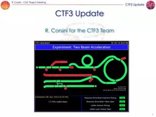
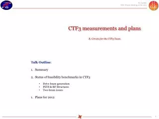
CTF3 measurements and plans R. Corsini for the CTF3 Team. Talk Outline : Summary Status of feasibility benchmarks in CTF3 Drive beam generation PETS & RF Structures Two-beam issues Plans for 2012. 1. CTF3 - 2011.

E N D
CTF3 measurements and plansR. Corsini for the CTF3 Team • Talk Outline: • Summary • Status of feasibility benchmarks in CTF3 • Drive beam generation • PETS & RF Structures • Two-beam issues • Plans for 2012 1
CTF3 - 2011 • Many improvements on optics, hardware, feed-backs, beam stability, reproducibility… • PETS operation to power levels (~250 MW) well above CLIC goal, at nominal CLIC pulse length. • Measured gradient in two-beam acceleration test 145 MV/m (CLIC nominal gradient of 100 MV/m) • Nine PETS tanks installed in the Test Beam Line (TBL), 20 A decelerated by ~ 25%, matching well with expectations • First successful test of PETS with on-off mechanism • First measurements of break-down kicks in TBTS Optics model checks in Combiner Ring 12 GHz RF power Power Extraction Structure (PETS) P [MW] 135 MW Two-beam acceleration in TBTS t [ns] CLIC target pulse Test Beam Line (TBL) in CTF3
Many, many thanks to the CTF3 team & all collaborators from within & outside CERN • Barranco Javier • Constance Benjamin • Ikarios Emmanouil • Persson Tobias • Skowronski Piotr • Sterbini Guido • Bolzon Benoit • Burger Stephane • FavierMathilde • Guillot-Vignot Franck • Lefevre Thibaut • OlvegaardMaja • RabillerAurelie • SobyLars • Dobers Tobias • Chevallay Eric • Csatari Marta • FedosseevValentin • HesslerChristoph • Draper Michael • GambaDavide • Tecker Frank • Dubrovskiy Alexey • Pasinelli Sergio • RiddoneGermana • SamochkineAlexandre • Kovermann Jan • Kononenko Oleksey • Andersson Alexandra • Curt Stephane • Doebert Steffen • Geschonke Gunther • Livesley Stephen • Mcmonagle Gerard • Barnes Michael John • Hourican Michael • De Oliveira Loic • David Nicolas Andre • Putz Sven • PajuEsa Antero • Allard Daniel • Monteiro Jose • Ravida Gianfranco • Rey Stephane Franck • Rinolfi Louis • Rossat Ghislain • Syratchev Igor • Timeo Luca • Wiszniowski Thierry • Farabolini Wilfrid • Peauger Franck • Ruber Roger • Palaia Andrea • Gerbershagen Alexander • Marin Lacoma Eduardo • LillestolReidar • JacewiczMarek • …
CLIC Feasibility Benchmarks CTF3 Nextef– RF test stand KEK RF Test Stands SLAC – KEK -CERN Technical system tests and simulations 4
Achievements – Drive Beam Generation Dipole modes suppressed by slotted iris damping (first dipole’s Q factor < 20) and HOM frequency detuning MKS05 MKS03 MKS06 MKS07 RF pulse at structure input 1.5 µs beam pulse RF pulse at output Spectrometer 4 Spectrometer 10 damping slot 10 m SiC load High current, full-loaded linac operation • 95 % RF to beam efficiency measured • No instabilities
Achievements – Drive Beam Generation Beam recombination • Fast bunch phase switch in SHB system • Operation of isochronous rings and beam lines
Achievements – Drive Beam Generation 333 ps 83 ps x t Streak camera image of the beam, illustrating the bunch combination process
Achievements – Drive Beam Generation P , n 0 0 Transverse RF Deflector, f 0 2 P , 2 × × f 0 0 P , f 0 0 Deflecting Field Beam recombination • Factor 8 recombination by RF deflector injection 6& 7 December 2011
Achievements – Drive Beam Generation • Problems: • TWT availability – still working with 2 SHB only – plus day-to-day power fluctuations • Mainly working with 3 GHz beam for most of the year • Difficult DL set-up after last stop – suspect misaligned quadrupole (+ radiation alarm problem) • Eventually able to get good recombination (current record), but: • Bad pulse shape (phase switches?) • Still limited acceptance -> stability was improved, but it is still not good enough • Future work: • Measure and realign DL quad(s) • Work on phase switches, gun current compensation, back to 3 TWTs, improve trajectories DL current H V P. Skowronski
Achievements – Drive Beam Generation Measurements in TL2 - uncombined Beam recombination - Emittance Best results in CLEX for factor 4: eH= 250 um eV= 140 um for factor 8: eH= 640 um eV= 170 um Different turns are ~ ok, no unknown effects Emittance increase due to non perfect combination Horiz. Vert. • Improve measurements • Correct dispersion (linear, nonlinear) • Correct multi-turn orbit • Control beta-beating • End 2011 ? Uncombined beam
Achievements – Drive Beam Generation Vertical Horizontal Factor 4 Factor 8 Factor 4 Factor 8 • Emittance – last measurements in CLEX • No time for optimization • Main issue: different trajectories for DL & bypass beams and ring orbit closure (differences of the order of 1 s) • Vertical: main effect from DL, small effect from ring • Horizontal: ring closure is dominant • Similar Twiss parameters for factor 4 and factor 8 combination (small betatron mismatch) F. Tecker, P. Skowronski, S. Doebert, R. Lillestol
Achievements – Drive Beam Generation Beam profile during emittance measurements Factor 4 Factor 8 Improved quad scan program B. Constance
Achievements – Drive Beam Generation Beam recombination – Bunch lenght nominal in CLEX 1 mm sigma In the past, well below 1 mm sigma measured at the end of the linac (tuned chicane) Recent results (preliminary): 1.5 to 4 mm sigma for CR and CLEX (natural chicane) • Improve measurements • Tune chicane to small R56 • Measurements in CLEX • End 2011 ? Improve in 2012
Achievements – Drive Beam Generation Emittanceεx,y≤ 150μm Transverse jitter ≤ 0.3σ CLIC Drive Beam requirements Current stability 0.75 10-3 Phase stability 0.2° @ 12GHz Bunch length stability 1% RF power stability 0.2% RF phase stability 0.05° Current stability 0.1% Phase stability 2.5° @ 12GHz 0.2° @ 1GHz
Achievements – Drive Beam Generation Pulse charge measured at end of the linac After factor 8 combination ~ 1% jitter • “Good” CTF3 klystron • pulse-to-pulse jitter • 10 ns time slices along the RF pulse • with respect to local phase reference • Improve and document current stability for combination factor 4 • Improve stability for combination factor 8 – at the permil level • Means: improve acceptance (dispersion, orbit, beta-beating) • Reduce energy spread – bunch length • End 2011 – Mid 2012 G. Sterbini, A. Dubrovsky
Achievements – Drive Beam Generation Charge stability – Factor 4 3 to 4 10-3 1 10-3 5 10-4 18th November 2011 T. Persson
Achievements – Drive Beam Generation Charge losses – Factor 4 BPIs Total loss from cleaning chicane to TBTS ~ 15% BPMs 18th November 2011 T. Persson
Achievements – Drive Beam Generation Charge stability – Factor 8 1 10-2 DL ~ 1 10-3 6th December 2011 T. Persson
Achievements – Drive Beam Generation Charge stability – Factor 4 with noise estimate < 1 10-3 6th December 2011 T. Persson
Achievements – Drive Beam Generation Feed-backs, stability RF power feedback, MKS 13 [MW] [arb] Tobias Persson, Piotr Skowronski
Achievements – Drive Beam Generation Feed-backs, stability RF power feedback, effect on beam Tobias Persson, Piotr Skowronski
Achievements – Beam driven RF power generation • Analyze data for evaluation of present break-down rate • Dedicated measurement at high powers – increased rep rate • Document • End 2011 – Mid 2012 PETS rapidly (~ 3 x 10⁵pulses) reached record >200 MW peak RF power level, providing reliably pulses ~ 1o0 MW peak to accelerating structure. About twice the power needed to demonstrate 100 MV/m acceleration in a two-beam experiment with TD24 structure. Breakdown rate ? CLIC target pulse 22
Achievements – Beam driven RF power generation • Issues: • Reliable power production • Ability to control output power • Conditioning • Initial test – no structure connected • Connect structure • Full test, including use as recirculation loop • End 2011 ? On-off mechanism Installation in CTF3 TBTS under way now. Test starting from next week. 23
Achievements – Beam driven RF power generation PETS On-Off concept In CTF3 a movable short is added, to allow for recirculation mode ON Power extracted from the drive beam Power to the structure OFF Igor Syratchev, Alexei Dubrowski
Achievements – Beam driven RF power generation TBTS PETS layout with internal recirculation to test the ON/OFF concept Variable reflector (to tune the recirculation coupling) PETS output Structure input ON OFF Movable RF short circuit (to tune the resonant length) (as predicted by computer simulation) Igor Syratchev
CTF3 Achievements – Beam driven RF power generation Vacuum gauges Power 80 MW 45 MW PMT signal Peak power Current 30 October (logbook pictures) Pulse length at 50% level 150 MW PETS On-Off conditioning Igor Syratchev, Alexei Dubrowski
CTF3 Achievements – Beam driven RF power generation PETS On-Off operation – high current, high power Igor Syratchev, Alexei Dubrowski
Achievements – Beam driven RF power generation PETS On-Off mechanism - results Beam current PETS, forward RF Combination x 4 0N Simulation vs. experiment 0FF PETS output, forward PETS, reflected RF RF to structure 0N 0FF 0N 0FF Spectra comparison Signal evolution during On-Off Igor Syratchev, Alexei Dubrowski
Achievements – Beam driven RF power generation • Deceleration with 9 PETS, 20 A (end 2011) • Deceleration with 12 PETS, > 20 A (mid 2012) • Final test, 16 PETS (end 2012) 9 PETS – 20 A November 2011 16 PETS maximum 4 PETS installed and tested 45beinginstalled in September 12 to 16 next year • Up to 19 A current • optics understood • no losses in TBL • Good agreement • power production • beam current • beam deceleration 29
Achievements – Beam driven RF power generation Steffen Doebert, ReidarLillestol High current transport in TBL Factor 8 Factor 4 TL2 TBL Factor 8
Achievements – Beam driven RF power generation High current power production in TBL ReidarLillestol More than half a GW of 12 GHz power!
Achievements – Beam driven RF power generation ~ 30 MeV 25% Steffen Doebert Incoming energy 117 MeV, field form factor 0.9 (average)
Achievements – Beam driven RF power generation Beam loading compensation ramp • Create precise ramp by fine tuning of phase switches timing • Show control of ramp to the desired degree (limited by number of free parameters) • Eventually test acceleration with probe beam (short pulse, scan method) CLIC target pulse • Initial tests, end 2011 • Eventual improvements/upgrades, shut down 2011/2012 • Full test, including probe beam acceleration, mid/end 2012 2012 33
Achievements – Two-Beam Acceleration Two-Beam Acceleration demonstration in CTF3 Two-Beam Test Stand TD24 Drive beam ON Drive beam OFF Maximum probe beam acceleration measured: 31 MeV Corresponding to a gradient of 145 MV/m 34
Achievements – Two-Beam Acceleration Break-down kicks Andrea Palaia, WilfridFarabolini, Javier Barranco Measured on OTR screen CA.MTV0790 (~4.9 m from the accelerating structure). kick angle = 340 µrad kick angle = 400 µrad
Break-down kicks, distribution Andrea Palaia
Achievements – Accelerating Structures • Continue conditioning/BDR measurements of TD24 in the shadow of other experiments • Profit to improve power production stability/availability/rep rate • Continue BD kick measurements • Install couple of new structures, TD24 with wake-field monitors in winter shut-down 2011-2012 • First module should go in during winter shut-down 2012-2013 37
Achievements – Accelerating Structures New Data Alexei Dubrowski WilfridFarabolini 38
CTF3 Achievements – Drive Beam CTF3 Achievements – What is still missing for feasibility – Drive Beam Generation Ring isochronicity ap < 10-4 Transverse rms emittance 100 p mm mrad (end of linac) Bunch length control < 1 mm rms (end of linac) Factor 2 combination in Delay Loop (from 3.5 to 7 A) Control of ring length to better than 0.5 mm Beam current stability ~ 0.1 % end-of-linac, ~0.2 % combiner ring Bunch train recombination factor 4 in Combiner Ring (from 3 to 12 A) ~ 0.1 % factor 4 ~ 0.1% factor 2 after DL ~ 0.05 % end-of-linac ! Full beam loading (95% transfer) high current acceleration (up to 5 A) Bunch train recombination 2 x 4 in DL and CR (from 3.5 to 28 A) Transverse rms emittance < 150 p mm mrad (combined beam) Bunch length control < 1 mm rms (combined beam) Beam current stability ~ 0.2 % for fully combined beam Sub-Harmonic bunching with fast (< 6ns) 180 phase switch (8.5% satellites) ~ 1 % 39
CTF3 Achievements – Two-Beam issues CTF3 Achievements – What is still missing for feasibility – TBL / TBTS / CALIFES 8 (12 > 16) PETS + spectrometer installed to verify transport of a 28 A beam with up to 30% of energy extracted. Probe beam acceleration to 100 MV/m. (up to 145 MV/m measured) 9 PETS 20 A beam 25% deceleration Beam-powered test of a PETS to nominal parameters (135 MW, 240 ns) with external recirculation (10 A) and without (20 A) – including probe beam Improved power & drive beam energy loss measurements Break-down kick measurements PETS On-offmechanismdemonstration Drive beam phase Beam-powered test of a PETS with external recirculation to 170 MW, <200 ns - ~10 A beam current Power & drive beam energy loss measurements. 40
Outlook • Drive Beam: • Flatness, RF pulse shape control (main beam loading), • Charge & energy stability) • Emittance • Bunch length • Phase monitor qualification, DB phase stability studies • TBL: • - 12 PETS, > 20 A deceleration • Dispersion free steering, optics studies • Possibly, new PETS prototype for TBL+ (input coupler, mini-tank) • TBTS: • - PETS on/off final test, BDR control • New structures, conditioning & BDR measurements • Wakefield monitors tests • BD studies (flashbox) • Continuation of BD kicks measurements
Accelerating Structure - Experimental results Breakdown rate at 100 MV/m (unloaded) accelerating gradient and scaled to 180 ns pulse length Measurements scaled according to Damped SLAC Tests KEK Tests CTF3 Two-Beam 1st generation, moderate efficiency 2nd generation, high efficiency CERN built, old procedure Undamped 43
Beam Recombination Factor 8 Factor 4
Gun current Correction Alexandra Andersson
Compensation of phase switches Gun adjusted, no switches Switches, gun re-adjusted Switches introduced Alexandra Andersson, Frank Tecker, Piotr Skowronski
Compensation of phase switches No switches Switches Frank Tecker, Piotr Skowronski
Optics studies, orbit correction Model checks in CR Guido Sterbini, Ben Constance Orbit correction in TL1 - CR Ben Constance
TBL with 9 PETS tanks Steffen Doebert, ReidarLillestol
TBL with 9 PETS tanks ReidarLillestol