FAA Pavement Design
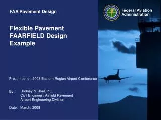
FAA Pavement Design. Flexible Pavement FAARFIELD Design Example. 2008 Eastern Region Airport Conference. Rodney N. Joel, P.E. Civil Engineer / Airfield Pavement Airport Engineering Division. March, 2008. FAARFIELD Flexible Pavement Design. FAARFIELD Flexible Pavement Design.


FAA Pavement Design
E N D
Presentation Transcript
FAA Pavement Design Flexible Pavement FAARFIELD Design Example 2008 Eastern Region Airport Conference Rodney N. Joel, P.E. Civil Engineer / Airfield PavementAirport Engineering Division March, 2008
FAARFIELD Flexible Pavement Design • Starting Screen – No Job Files Created Click on “New Job”
FAARFIELD Flexible Pavement Design • Creating / Naming a Job File Enter Job Title Click OK
FAARFIELD Flexible Pavement Design • Copy Basic Section/Pavement Type from Samples Click on “samples”
FAARFIELD Flexible Pavement Design • Copy Basic Section/Pavement Type from Samples Default Basic Pavement Sections Click on “Copy Section”
FAARFIELD Flexible Pavement Design 7 Basic Starting Structures in LEDFAA • Section Name Pavement Type • ACAggregate New flexible on Aggregate base • AConFlex Asphalt overlay on Flexible pavement • AConRigid Asphalt overlay on Rigid pavement • NewFlexible New Flexible on stabilized base • NewRigid New Rigid on stabilized base • PCConFlex PCC overlay on flexible • PCConRigid Unbonded PCC on rigid • Be sure to select the pavement type that most correctly represents your pavement needs
FAARFIELD Flexible Pavement Design • Copy a Typical Pavement Section Click on desired pavement section Then click on the project where the section will besaved
FAARFIELD Flexible Pavement Design • Create a New Job Title Enter Job Title Click OK
FAARFIELD Flexible Pavement Design • Create a New Job Title Click “End Copy”
FAARFIELD Flexible Pavement Design • Working With a Design Structure Select the job and then select the sectionyou want to analyze Click on “Structure” To open the file
FAARFIELD Flexible Pavement Design • Working With a Pavement Section The selected sample pavement will appear The structure may be modified if desired
FAARFIELD Flexible Pavement Design • Modifying a Pavement Section Click on the boxaround the layer material you wantto modify
FAARFIELD Flexible Pavement Design • Modifying a Pavement Section Select the layer type you want to include in your pavement section No modificationfor this example Click OK Cancel for this example
FAARFIELD Flexible Pavement Design Layer Placement Restrictions • There are restriction on placement of certain pavement layers. • e.g. You can not place an “overlay” below a “surface” course. • Other restrictions prevent or cause changes in the pavement type (flexible or rigid) • e.g. Changing a surface asphalt layer to a rigid layer will change the pavement type.
FAARFIELD Flexible Pavement Design • Modifying a Pavement Section Click on a property tomodify any of the layer properties Modify the subgradeCBR for this example
FAARFIELD Flexible Pavement Design • Modifying a Pavement Section Enter the new valuefor the material property ** some materialswill have limits on property valuesuse 8 for this example Click OK
FAARFIELD Flexible Pavement Design • Modifying a Pavement Section New values appearin the structure window Click End Modify
FAARFIELD Flexible Pavement Design • Enter Traffic Mixture Click on “Aircraft” To enter traffic mix
FAARFIELD Flexible Pavement Design • Enter Traffic Mixture You may want toclear any existingairplanes Click on the airplanegroup desired. Then select the desired airplaneand click “Add” Repeat for completetraffic mixture
FAARFIELD Flexible Pavement Design • Traffic Mix for this example
FAARFIELD Flexible Pavement Design • Enter Traffic Mixture Certain airplanes mayappear in the list twice. This is to address thepresence of wing gearsand belly gears FAARFIELD treats these as two airplanes however the weightand departures areinterlocked
FAARFIELD Flexible Pavement Design • Adjusting Airplane Information Gross Taxi Weight, Annual Departures and % Annual Growth may be modified
FAARFIELD Flexible Pavement Design • Adjusting Airplane Information – Gross Weight Click on the airplanegross weight to change the weight
FAARFIELD Flexible Pavement Design • Adjusting Airplane Information – Gross Weight Enter the newweight and clickOK
FAARFIELD Flexible Pavement Design Airplane Information – Gross Weight Limitations • There are limitations on changes to airplane gross weights. • A range is provided for each airplane which represents reasonable weights for the airplane
FAARFIELD Flexible Pavement Design • Adjusting Airplane Information – Annual Departures Click on “AnnualDepartures” to change departures for an airplane
FAARFIELD Flexible Pavement Design • Adjusting Airplane Information – Annual Departures Enter the annualdepartures of theairplane Click OK
FAARFIELD Flexible Pavement Design Annual Departures in FAARFIELD • Annual departures has the same meaning as the previous design procedure. • Arrivals are ignored. • For design purposes FAARFIELD uses the total annual departures, adjusted for growth, multiplied by the total design period in years e.g. 1200 annual departures X 20 years = 24,000 departures
FAARFIELD Flexible Pavement Design • Adjusting Airplane Information – % Annual Growth of Annual Departures Click on the annualgrowth value tobring up the pop-upbox. Enter the percent annual growth and click OK
FAARFIELD Flexible Pavement Design Adjusting Airplane Information – % Annual Growth of Annual Departures You can create the same effect by modifying the annual departures such that the total annual departures results in the desired total. Allowable range of percent annual growth is +/- 10%
FAARFIELD Flexible Pavement Design • Viewing Airplane Information Scroll over to revealadditional columnsof information
FAARFIELD Flexible Pavement Design • Airplane Information Available in FAARFIELD Aircraft Screen
FAARFIELD Flexible Pavement Design • Viewing Airplane Information CDF columns andP/C ratio will be zero when airplanesare first entered Save the list whenfinished entering airplanes then click the back button
FAARFIELD Flexible Pavement Design • Performing the Pavement Design The layer with thesmall arrow is thelayer that will be adjusted to providethe structural design The location of the arrow is determinedby the type of pavement structure
FAARFIELD Flexible Pavement Design Layered Adjusted During Design • For New flexible sections the arrow can be moved by double clicking next to the desired base or subbase layer during “modify design” mode.
FAARFIELD Flexible Pavement Design • Design Life Click on the “des. Life” to change number of years for the design period. When the pop-up box appears, enter the desired number of years. NOTE: the standard FAA design is for 20 years
FAARFIELD Flexible Pavement Design • Performing the Pavement Design You are now readyto design the structure. Simply click on “Design Structure” The program will keep you informedabout the status of the design
FAARFIELD Flexible Pavement Design • Result of the Pavement Design The program will adjust the design layer until a CDF of 1.0 is achieved
FAARFIELD Flexible Pavement Design • Result of the Pavement Design The program has also determined theminimum base layer requirement
FAARFIELD Flexible Pavement Design • Reviewing Airplane Data After Completing the Design CDF and P/C ratio information is now available This information allows you to see which airplane have the largest impact on the pavement structure
FAARFIELD Flexible Pavement Design • Saving and Reviewing the Pavement Design Data When finished with the design, click the “Back” button and select whether you want to save the data
FAARFIELD Flexible Pavement Design • Reviewing Design Information To view a summary of the design click the “Notes” button
FAARFIELD Flexible Pavement Design • Reviewing Design Information You can view the summary data or copy it to other electronic media Data can also be exported in XML to allow automated entry into FAA Form 5100
FAARFIELD Flexible Pavement Design • Reviewing Design Information
FAARFIELD Flexible Pavement Design • Reviewing Design Information Notice the Statement “Asphalt CDF was not computed” This means the design assumed the failure was in the subgrade and did not calculate the fatigue in the bottom of the asphalt layer
FAARFIELD Flexible Pavement Design • Calculating Fatigue in the Asphalt Layer By clicking the options box the user can access the optional program features including the Asphalt layer CDF
FAARFIELD Flexible Pavement Design • Calculating Fatigue in the Asphalt Layer If you want the program to calculate the asphalt fatigue un-check the box and re-run the design
FAARFIELD Flexible Pavement Design • Calculating Fatigue in the Asphalt Layer As this example demonstrates, the controlling feature is almost always the subgrade i.e. subgrade CDF reaches 1.0 while the AC CDF is still 0.0
FAARFIELD Flexible Pavement Design Minimum Base Course Requirements • FAARFIELD will automatically determine the minimum base layer requirements. • Users can do this step manually if desired by deselecting this option • Remove subbase layer and increase subgrade CBR to 20. • Re-run the design to obtain the minimum base thickness