Download
1 / 18
200 likes | 402 Vues
Process Overview After a gas well is completed the gas is typically drawn from the well via a self containing portable skid containing a driver, compressor and separation devices. Care needs to be taken to remove the liquids and solids from the gas stream prior and post

E N D
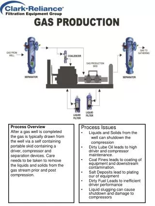
Process Overview After a gas well is completed the gas is typically drawn from the well via a self containing portable skid containing a driver, compressor and separation devices. Care needs to be taken to remove the liquids and solids from the gas stream prior and post compression. Process Issues Liquids and Solids from the well can shutdown the compression Dirty Lube Oil leads to high driver and compressor maintenance. Coal Fines leads to coating of equipment and downstream contamination. Salt Deposits lead to plating our of equipment Dirty Fuel Leads to inefficient driver performance Liquid slugging can cause shutdown and damage to compressors
Process Overview Gas from production field is collected via inter-connecting pipelines to Dehydration plants where the water is removed and in some cases where H2S and CO2 is removed as well. Keeping the solid and liquid contaminates out of the processing plant is the most important portion of gas gathering. Process Issues Contaminated inlet gas causes excessive element usage and foaming in contactor towers. Contaminated inlet gas causes excessive solvent use. Contaminated inlet gas make the contactor towers inefficient Solvent contamination can cause plating out or plugging of the heat exchangers. Poor solvent performance leads to off spec gas
Process Overview Gas Transmission stations are designed to increase the pipeline pressure and move the gas through out the pipeline grid. Stations are normally every 50 to 100 miles along the pipeline and contain drivers (turbines) and compressors plus the support equipment such as separators, filter separators and coalescers. The support equipments purpose is to clean the gas coming into and departing the transmission station. Process Issues Gas contamination fouls compressors Gas Contamination in the fuel gas stream causes hot spots in the turbine combustion chamber leading to short life. Contaminate in the coolant leads to driver inefficiency Oil Carryover from the compressor clogs downstream equipment Carryover from Glycol Dehydrator causes compressor and downstream problems
Process Overview Amine Sweetening utilizes solvent to remove H2S and CO2 which are both harmful to the pipeline and equipment. Process Issues Contactor Foaming Heat Exchanger Fouling Heater Tube hot spots Extreme corrosion on heating surfaces Increased maintenance costs Increased solvent usage Formation of heat stable salts Activated carbon fouling Waste disposal increase costs pH fluctuation due to acid gas formation Cyanide Formation Condenser fouling Sulfur recover catalyst damage
Process Overview Sulften is a Claus tail gas treating process designed to treat gas with less than 20% CO2. As gas enters the system it is heated to reaction temperature where it becomes hydrolyzed and hydrogenated to covert the SO2 producing H2S and water. Gas is then cooled and passed into the first of two towers to selectively remove the H2S. The sour water from the stripper tower is piped to the sour water stripper and selective solvent is stripped. The absorber gas is almost pure CO2 while the stripper produces almost pure H2S which is sent back to the Claus process for Sulfur recovery. Process Issues Corrosion Iron Sulfides Elemental Sulfur Quench Water Solids Solvent pH Solvent loss downstream NOx levels up Contactor Foaming Solvent contamination in the rich side causes most tail gas treating problems.
Process Overview Shell Claus Off Gas Treating (SCOT) process is a wet scrubbing process designed to remove sulfur compounds from Sulfur Plant tail gas through amine absorption. The H2S removed is returned to the front end of the Claus unit for sulfur recovery. Protection of the catalyst bed is vital, you should assure that both liquids and solids are removed from the gas stream to prevent premature Catalyst bed decay. Process Issues Amine carryover Cooler Fouling Pipeline corrosion Catalyst Bed Fouling Tower corrosion Compressor life effected
Process Overview Large skid mounted engines drive compressors, these engines generate a great deal of heat that needs to be dissipated or it will cause eventual engine failure. This heat is dissipated with the use of coolants, normally ethylene glycol/water or propylene glycol mixture. These coolants become contaminated with oils, solid particulate and other foreign material. These contaminates lead to performance problems and short engine life. Process Issues Short coolant life Pump seal wear Thermostat malfunction Cylinder wear Valve wear
Process Overview Over time solid waste in landfills decomposes, during decomposition gas composed of carbon dioxide and methane is produced. Landfill gas has low heating value (500-550 BTU) this gas is collected under vacuum through a system of vertical wells sometimes using horizontal headers. After this gas is cleaned it can be used to generate electricity. Process Issues Corrosion Condensation and forming nasty liquid hydrocarbons Compressor wear due to liquids and corrosion
Process Overview Pipeline gas is seldom treated after the last compressor station therefore gas entering plants can contain a variety of solid and liquid contaminates such as pipeline additives i.e. corrosion inhibitors, odorizers, hydrate inhibitors, and antiscalants. It is vital to remove these contaminates prior to introducing gas to the process heaters. Process Issues Heater Nozzles fouling Compressor wear and maintenance Heater inefficiency
Process Overview Generation of power by Natural Gas driven turbines continues to grow worldwide. Most straight turbine generators are known as “peakers” or are used to power a specific plant that has no practical use for steam. Process Issues Cleanliness of the fuel gas Coolant filtration Lube oil Filtration Air Filtration
Process Overview Combined Cycle Electrical Power generation is utilized to capture as much output energy as possible from the energy consumed. Electricity is generated and goes to the power grid while the exhaust gas is directed to a boiler which produces steam. The steam is then used to drive a steam turbine to generate additional electricity which is fed to the power grid as well. Process Issues Fuel Gas Contamination Air Contamination Compressor lube oil contamination Turbine lube oil contamination Steam system make up water contamination
Process Overview Coal Fired Power Plants generate more electricity worldwide than any other type of generation system. In this process the coal is pulverized to a powder and conveyed into a boiler along with preheated air where it is burned to generate heat. The boiler contains heat exchanger tubes filled with water. The water in these tubes is converted to steam which is used to drive steam turbines which generate electricity. Process Issues Calcium and Magnesium scaling from poor quality make up water Plugging of the high pressure ash wash nozzles Turbine reliability due to lube oil contamination Turbine reliability due to poor quality steam
Process Overview Pressure relief, incinerator gases and some off gases are normally flared at most refineries. Process Issues Flame Arrester Failure Burner Tip Fouling Pilot Flame Outs Burner Flame Outs Flash Back Explosions Excessive release of contaminates into the atmosphere.
Process Overview Catalytic Reforming utilizes low octane naphtha in the presence of Hydrogen to produce high octane motor fuel blending stock. By- products of this process are Aromatic intermediates Process Issues Process liquid carryover Reactor bed plugging Reactor bed short life Catalyst carryover
Process Overview Hydrotreater feedstock's normally contain sulfur, N2, Asphaltines and metals. Quality fuel oil and catalytic cracker feedstock's are produced by removing the contaminants through hydrogen and solid catalyst treatment. Process Issues Reactor Fouling Hydrogen compressor failure/high maintenance Recycled hydrogen contamination
Process Overview Hydrocracking is the process which can be used to reduce any petroleum fraction to any product of lower molecular value. During hydrocracking N2, sulfur and O2 are removed from the hydrocarbon resulting in product mixtures of naphthalene's, aromatics and paraffin's Process Issues Catalyst bed fouling Heat Exchanger fouling Reactor Bed damage/plugging Liquid carryover from separators Heat exchanger fouling
Process Overview Solid desiccants such as alumina, aluminum or silica gel and molecular sieves are used to absorb moisture from natural gas. Water in the gas is removed prior to the gas being introduced to the desiccant bed. Gas is preheated and introduced into the bed to remove trace moisture, when the bed is saturated a switch to the other bed occurs and the used bed is regenerated. Process Issues Bed fouling from hydrocarbon introduction Bed fouling from solids introduction Amine and glycol contamination Iron sulfides introduction Corrosion inhibitors introduction COALESCER COALESCER
Process Overview Isomerization process produces catalytically converted straight chain paraffin hydrocarbons into isomers in a hydrogen rich environment. The more complex isomers have a higher octane rating and are used as blending compounds for motor fuels Process Issues Stabilizer internals fouling Scrubber carryover Catalyst Bed Plugging Mol Sieve Bed Plugging