Download
1 / 2
20 likes | 124 Vues
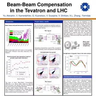
Explore the application of the Tevatron Electron Lens (TEL) in reducing beam losses through straight magnetic lines, achieving linear Beam-Beam Compensation. Learn about the tune spread, magnetic field quality measurements, challenges, and future plans in accelerator technology.

E N D
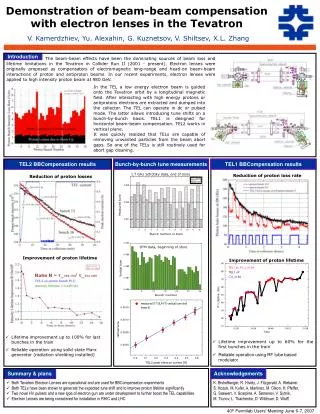
Straightness of magnetic lines in the main solenoid TEL2 Bunch-by-bunch tune spread as a result of parasitic beam-beam interaction one TEL Run II Goal two TELs 2 nonlinear TELs Yu. Alexahin, V. Kamerdzhiev, G. Kuznetsov, V. Scarpine, V. Shiltsev, X.L. Zhang, Fermilab Beam-Beam Compensation in the Tevatron and LHC Introduction Project status, results TEL2 has been tested prior to installation in the Tevatron. Magnetic field quality was measured using a hall probe and a laser based method. The second method utilizes a laser which is aligned along the solenoid axis. Its light is reflected by a magnetic mirror which is mounted on a cart dragged through the solenoid. The light is detected by means of a position sensitive detector. Since the mirror aligns itself perpendicular to magnetic field lines, the measured light spot position is a measure of magnetic line straightness. Measured straightness agrees with initial specification. TEL one has been operated successfully to perform BBComp studies and became an operational device for abort gap cleaning. Beam losses and peak luminosity in the Tevatron TEL1 layout Mirror used to measure magnetic line straightness Calculations showed that a second TEL is needed in order to efficiently reduce tune spread in both planes Effects associated with both head on and parasitic beam-beam interaction have been observed in the Tevatron. Calculated pbar tune spread Development of electron guns TEL1 was initially equipped with a high perveance gun that features uniform (flat) transverse charge distribution. Beam studies using this gun showed tune shifts up to 0.009 accompanied by high losses due to edge effects. A “gaussian” gun was introduced in 2002 and allowed to greatly reduce losses. To make e-beam alignment less critical and to increase the perveance a new smooth-edge-flat-top (SEFT) gun was commissioned in 2005 showing a good compromise between perveance and electron beam profile for linear BBComp. TEL2 layout The goal of linear Beam-Beam Compensation (BBComp) is to reduce beam losses by reducing bunch-by-bunch tune spread. Bunches circulating in the machine have to be treated individually. A device called Tevatron Electron Lens (TEL) has been designed and installed in 2001. Pulsed electron beam is placed on pbar/proton orbit. A number of beam studies showed tune shifts up to 0.009.
Page 2 e-beam profiles, measured and calculated BBComp in LHC dQx vs horizontal e-beam displacement After intensity upgrade in the LHC head on beam-beam compensation can become beneficial. How does it work? • Electrons compensate protons – that’s good! • DC beam no HV pulsers, • Need 2 lenses – one per beam at equal beta’s • Large beta is ~OK • E-beam profile should be Gaussian (rms 0.3-0.5 mm) to match protons at IPs – can be done • Need dQ_max~0.01 - achievable Feb 17th, 2006 beam study EoS 1x1 store 40 pi emittances Improvement of BPMs Electron compression of head on footprint (calculated for pbars) TEL1 BPMs (diagonally cut cylinders) are known to report different position depending on beam pulse width. The difference can be up to 1.2 mm. dQx vs vertical e-beam position TEL1: beam position vs pulse width Tunes are given in units of head on beam-beam parameter. Numbers in parentheses show hor and vert betatron amplitudes in units of rms pbar beam size. The case with electrons is shifted for clarity. Using SEFT gun lifetimes of 700 hrs with dc e-beam and 340 hrs in pulsed regime have been observed. Presence of e-beam does not effect life time significantly. However, losses occur while tuning e-beam. Typically peak e-current was in the range 0.7-2 A. TEL2 BPM design utilizes four plate geometry with grounded electrodes between the plates to reduce crosstalk. They have been calibrated using a stretched wire and electron beam pulses of different width. The accuracy is better then 0.2 mm. For LHC Np=1.111, Nip=4, for 10kV electrons (ß=0.2) one needs Je=1.2 A and 3 m long e-beam TEL2 BPM performance, stretched wire Plans Optimized (6-Gauss) Gaussian • Assemble two more SEFT guns (in manufacturing) • Commission TEL2 in the Tevatron • Find an alternative way to clean the abort gap • Use both TELs for Beam-Beam compensation • Compensate many/all bunches simultaneously at low peak e-currents • Improve e-beam stability/ripple to reduce losses • Perform simulations of: • Liftime vs e-beam alignment • How does the bend shape effect BBComp • Lifetime vs dispersion Just an example Measured tune shift and lifetime dQx vs e-current Challenges of head-on beam beam compensation • Total current is not a challenge • Optimum beam profile is important • Compression to 0.3-0.5 mm is doable, though not easy • Keeping beam straight within 0.03-0.05 mm • Beam-beam centering within 0.03-0.05 mm