Download
1 / 27
270 likes | 383 Vues
This project details the process of connecting a photoresistor sensor to a computer through a microcontroller, ultimately converting an analog signal to a digital one. The paper outlines the necessary components, including voltage dividers, op-amps, and microcontrollers. It describes how to set up a circuit that measures light intensity, compares signals using a 741 op-amp, and transports data through USB. Practical applications, like automated streetlights, demonstrate real-world uses for the system. This guide serves as an essential reference for electronics enthusiasts and students.

E N D
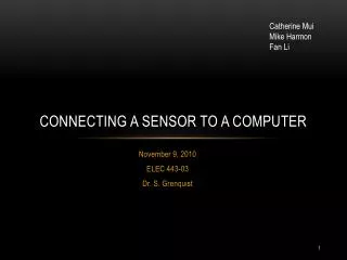
Catherine Mui Mike Harmon Fan Li Connecting a Sensor to a Computer November 9, 2010 ELEC 443-03 Dr.S. Grenquist
Parameters • Find an analog sensor • Interface the sensor with the computer • Get it done as soon as possible!
Types of Sensors • Photocell • Thermocouple • Pressure sensor • Photodiode • Thermistor • Infrared sensor
Photoresistor • Varying resistor dependent on light intensity • Made of high resistance semiconductor • Photons absorbed from the light give bound electrons energy to move to the conduction band • Free electrons increase current flow • Decreased resistance
Developing the circuit Use a voltage divider to vary the output voltage Figure 1 – Increased light increases voltage output. An analog output is produced due to the varying resistance of the photoresistor Figure 2 – Increased light decreases voltage output.
The choice In the brightest setting: In the darkest setting:
The Problem • Computers use digital logic • Unable to instantaneously read a varying voltage output Therefore, we must develop a way to convert the output to a digital signal
The options • Microcontroller • Write code to convert analog signal to digital signal • DAQ – Data Acquisition Unit • Built-in analog to digital converter • ADC Chip – Analog to Digital Conversion Chip • Construct a circuit • Comparator
Voltage comparator • Uses the 741 op-amp • The analog waveform is compared to the DC voltage supply • When the analog signal is larger than the DC voltage, the circuit outputs a HIGH • If lower, the output is a LOW
The 741 op-amp Pin Connections Not Connected DC voltage supply Voltage output from voltage divider Ground Not Connected Output +9V Not Connected
Obtaining the dc reference voltage • Want to use only one voltage source to supply the voltage across the photoresistor and to supply the reference DC voltage • Parallel input to a second voltage divider
Testing the circuit • What is the critical resistance between a high and low output? 4.5V • Example: In the lighting of the electrical lab, • < 10kΩ Low Output
Making the connection • Microcontrollers • Able to transmit information to the computer through a USB connection • Texas Instrument: MSP430 (16 Bits) • Atmel AVR (8-bit) • AVR32 (32-bit) • BasicX • Ardiuno • Parallax
Parallax Microcontroller • Complex device, however we barely got into its capabilities • Only used as interface between voltage output and computer • 3 pins used: • Relays information through USB port
Basic Stamp Software Download • Go on the Parallax website • http://www.parallax.com/tabid/441/Default.aspx • Click on Download on the top right corner
Basic Stamp • Click Save, when the file download shows up. • Install the software and wait for it to setup.
Basic Stamp • Once the software has been download. • Click Run • BASIC STAMP Editor screen • Click Next
BASIC STAMP • Starting Window • You can write the programming code in the white space provided.
Programming Code ' {$STAMP BS2}' {$PBASIC 2.0}Main:DO DIR0 = 0IF IN0 = 1 THEN PrintitIF IN0 = 0 THEN Printit1Printit:DEBUG HOME, "No Light On“PAUSE 100GOTO MainPrintit1:DEBUG HOME, "Light Is On"PAUSE 100GOTO Main
EquIpment • Photoresistor • 3 10kΩ resistors • 741 Op-amp • Breadboard • 9 Volt battery • Wires • Parallax microcontroller • BASIC stamp editor v2.5
Applications • A circuit like this can be used for devices that should be turned on when lighting is minimal • e.g. Street lights
References • http://itp.nyu.edu/physcomp/Labs/Components • http://en.wikipedia.org/wiki/Photoresistor • http://www.cybercollege.com/tvp008.htm • http://www.nteinc.com/specs/2000to2099/pdf/nte2053.pdf • http://www.ferret.com.au/c/Firetail-DAQ/New-USB-counter-timer-modules-available-from-Firetail-DAQ-n817104 • http://www.tmworld.com/article/323379-Create_short_pulses_with_a_function_generator.php • http://pixdaus.com/single.php?id=138442
THANK YOU FOR LISTENING! QUESTIONS?