Download
1 / 42
420 likes | 776 Vues
Calibration Assessment of INSAT Satellite Infrared Data Using NOAA Satellite Data. Gagandeep Kaur, Soma Sen Roy , A.K.Sharma Junior Research Fellow, IMD Scientist-D, IMD Scientist- F, IMD. INTRODUCTION.

E N D
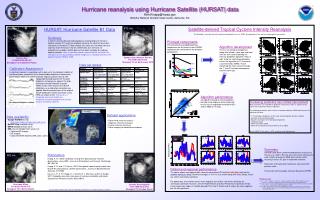
Calibration Assessment of INSAT Satellite Infrared Data Using NOAA Satellite Data Gagandeep Kaur, Soma Sen Roy , A.K.Sharma Junior Research Fellow, IMD Scientist-D, IMD Scientist- F, IMD
INTRODUCTION • India Meteorological Department is receiving and archiving satellite meteorological data from INSAT series since 1984. • Data is already archived on DLTs and resolutions of these data are 2.75 km/2km in visible, 11km/8km in infrared channels for INSAT-1/INSAT-2 series respectively. • The normalized calibration technique is attempted in order to re-calibrate the Kalpana-1 Infrared data and remove the effect of the temporal non-linearity of sensor response due to degradation of the sensor based on ISCCP (International satellite cloud climatology project) procedure over the Indian Ocean. • Table- KALPANA-1 Satellite Specification
DATA AND METHODOLOGY • Study Covers the months MAY, JUNE, JULY, OCTOBER, NOVEMBER and DECEMBER of 2009. • Taking 8-10 passes of NOAA of each month. • Four automated steps to satellite Inter-calibration :: • Data collection: • Study period: MAY, JUNE, JULY, OCTOBER, NOVEMBER, DECEMBER 2009. • Study region: ± 10º NS latitude of the equator; 64º-84º longitude east • Primary data for inter-calibration :: kalpana-1 Geostationary satellite VHRR Infrared brightness temperatures • Polar Orbiting Satellite used :: NOAA-19 AVHRR channel-4 brightness temperatures, data accessed through INCOIS, Hyderabad and its collection based on • currently operational satellite series • status of imager AVHRR • ISCCP survey on data availability
….Contd • The impact of spectral differences between the IR win channels is important to consider when comparing brightness temperatures to those from AVHRR. a) b) Fig a) Shows the spectral response function of NOAA-AVHRR channel-4 and b) Kalpana-1 Infrared respectively. • Study area of interest : • The strategy is to find the measurements by the polar orbiting satellite that are concurrent and collocated with those from a geostationary satellite. • The near-simultaneous nadir observations with homogeneous scenes from NOAA and Kalpana-1 imagers are spatially collocated.
…Contd • Domain of the earth for the study ::: ±10º NS latitude of the equator, 64º- 84º longitude east • Time differences between observations should be less than 30min. • Collocation Criteria :: Study Region selected for inter-calibration process • .
…Contd Table : data processing constraints • Nearest Neighbour distance Technique performs the linear search iteratively to find the closest point in the LEO satellite observations with the maximum outer threshold taken as 20 km. • Nearest Neighbour Formula used :: Where d is Euclidean distance; LatK , LonK , LatN and LonN are the latitude and longitude of Kalpana-1 and NOAA respectively. • For every fifth point of Kalpana-1 (latitude-longitude) in NOAA data, distance is calculated using above formula and simultaneously changing the threshold while iterating, if and only if distance is lesser than outer threshold (i.e. 20km). • The least distance point of NOAA AVHRR would be the best fitted collocation point for Kalpana-1 (latitude-longitude).
…Contd • Calculation :: • Linear Least Square equation is used to find coefficients (slope and intercept) . Y = m * X + c; or BTNOAA = m X BTKALPANA-1 + c Where “m” and “c” are: Where N is the total number of observations; X is the Kalpana-1 Infrared brightness temperatures and Y is the NOAA AVHRR channel-4 brightness temperatures. • Kalpana-1 data is re-calibrated to get the new corrected brightness temperatures for the Infrared channel data. NEWBTKALPANA-1=m x OLDBTKALPANA-1 + c
…Contd • Calculating the Confidence of limit using two-tailed test . For this “z” score is computed and state the Confidence of Limit. Where and µ is the mean of brightness temperatures of Kalpana-1 VHRR Infrared ( 10.5 µm-12.5µm) and NOAA AVHRR channel-4 ( 10.3µm-11.3µm) data respectively; σ is the total standard deviation; N is the total number of observations of collocated points. σA is the standard deviation of Kalpana-1 Infrared brightness temperatures; σB is the standard deviation of NOAA AVHRR Channel-4 brightness temperatures. NA is the total no. of observations of Kalpana-1 data; NB is the total number of observations of NOAA data. • Results :: • Linear Least Square Coefficients are calculated for three cases: • For whole defined region [ ±10º NS LATITUDE OF THE EQUATOR, 64º-84º LONGITUDE EAST ] • For those brightness temperatures of Kalpana-1 less than 273.15 K i.e. cloudy region • For those brightness temperatures of Kalpana-1 greater than 273.15 K i.e. Clear sky.
RESULTS • Table; Shows the slope and intercept of Kalpana-1 data for months MAY, JUNE, JULY, OCTOBER, NOVEMBER AND DECEMBER, 2009.
Table; Shows the Mean, Standard Deviation and Confidence of limit for Kalpana-1 infrared and NOAA AVHRR channel-4 Data for the following months of 2009.
Scatterplot of Kalpana-1infrared brightness temperatures versus NOAA AVHRR channel-4 brightness temperatures for whole defined region; MAY JUNE JULY OCTOBER NOVEMBER DECEMBER
Scatterplot Kalpana-1 infrared brightness temperatures versus NOAA AVHRR channel-4 brightness temperatures for CLOUDY REGION [ for those brightness temperatures of Kalpana-1 Infrared less than 273.15 K ] ; MAY JUNE JULY OCTOBER NOVEMBER DECEMBER
Scatterplot Kalpana-1infrared brightness temperatures versus NOAA AVHRR channel-4 brightness temperatures for CLEAR SKY [ for those brightness temperatures of Kalpana-1 Infrared greater than 273.15 K ] ; MAY JUNE JULY OCTOBER NOVEMBER DECEMBER
CAL-VAL TEST SITE GagandeepKaur Manish Paliwal, A.K.Mitra Junior Research Fellow Junior Research Fellow Scientist- C A.K.Sharma Scientist F
AIM To establish a Calibration and Validation (CAL/VAL) site for INSAT 3D satellite
Why Cal-Val Test Site is needed ?? To verify the post-launch radiometric calibration of satellite instruments. To monitor instruments performance over time.
CAL/VAL TESTED SITES The Following sites followed the key guidelines of QA4EO ( Quality Assurance framework for Earth Observation) Railroad Valley Playa, NV, USA, North America Ivanpah, NV/CA, USA, North America LSpec Frenchman Flat, NV, USA, North America La Crau, France, Europe Dunhuang, Gobi Desert, Gansu Province, China, Asia Negev, Southern Israel, Asia Tuz Gölü, Central Anatolia, Turkey, Asia Dome C, Antarctica
SELECTION CRITERIA FOR TESTSITE • The site should have high spatial uniformity, relative to the pixel size, to minimize the effects of scaling radiometric data and atmospheric adjacency effects due to light scattered from outside the target region, to the size of the entire test site. Table for Earth target types that are often used for post launch ground look calibration of satellite instruments.
… Contd • The site should have a surface reflectance greater than 0.3 in order to provide higher signal-to-noise ratio (SNR) and reduce uncertainties due to the atmospheric path radiance. • The surface properties of the site (reflectance factor, BRDF ( Bi-directional reflectance distribution function), should be temporally invariant. Otherwise, adequate accuracy would be obtained only if these properties were measured for every calibration. This implies that the site should have little or no vegetation. • The surface of the site should be horizontal and have nearly Lambertian reflectance. • The site should be located at high altitude (to minimize aerosol loading and the uncertainties due to unknown vertical distribution of aerosols), far from the ocean (to minimize the influence of atmospheric water vapour), and far from urban and industrial areas (to minimize anthropogenic aerosols). • The site should have cloud free and low precipitation characteristics. The low probability of cloud coverage also increases the probability of the satellite instruments imaging the test site at the time of overpass.
NORMAL RAINFALL MAPS OF THE TEST SITE – JAISALMER (Lat: 26.9 N ; Long: 70.9 E)
POST-LAUNCH CALIBRATION OF METEOROLOGICAL SATELLITE SENSORS C.R.Nagaraja Rae’, J. Chen*, J.T. Sullivan’, and N. Zhang* NOAA/NESDIS Office of Research and Applications, Washington, D.C., 20233, USA QSS Group Inc., 4500 Forbes Boulevard, Lanham, MD 20706, USA
TEST SITE SIZE:: • The size of the surface area to be sampled is selected depending on the imagers resolution (medium or high-resolution) • An area approximately equal to 3 sensor pixels should be considered a minimum with a further 2 pixels of similar terrain at its periphery. For example MERIS has a 300 m pixel size and so a site of around 1 x 1 km is ideal.
INSTRUMENTS USED ON THE TEST SITE • PORTABLE SPECTRO-RADIOMETER-Used to calculate Reflectance Factor of the test site surface. • SUN-PHOTOMETER-Used to determine aerosol optical depth and water-vapour content. • Instruments used for TuzGolu test site :: • ASD FieldSpec3 Spectroradiometer - Measurement aims: To perform radiance/reflectance measurements over the selected target area at different times with various sampling rates to determine the spatial/temporal uniformity and to obtain the radiometric characteristics of the site. • field portable • precision radiometer with a spectral range (350- 2500 nm) • designed to collect solar reflectance, radiance and irradiance measurements. • Spectral Resolution: 3 nm @ 700 nm, 10 nm @ 1400/ 2100 nm
… Contd • Set-up time: Approximately 90 minutes to set-up and 15 minutes to be dismantled. Transportation. They weight totally 47 kg. • Power Requirements: 12VDC NiMh high current rechargeable battery pack is required. It can be used for 4-5 hours. Charging time is 8 hours. • Gonio Radiometric Spectrometer System (GRASS) Measurement aims: To conduct a series of multi-angular spectral measurements of the surface, perform measurements at different solar zenith angles, perform measurements over the same surface on sequential days to determine the temporal stability, and perform diffuse irradiance measurements. • easily and quickly assembled in remote situations, • measures the Earth’s reflected sunlight over half a hemisphere, at 30-degree intervals i.e. 0°, 30°, 60°, 90°, 120°, 150°, 180°, on a series of seven arms. • Resolution: same as ASD radiometer; Set up time: about 2 hours to set-up, and similarly 2 hours to dismantle at the end of the day. The instrument is left assembled on site overnight to reduce construction time. • Power Requirements: To run the instrument requires some power – this is achieved through the use of the Petrol Generator.
… Contd Above Figure shows ASD FieldSpec3 Spectroradiometer • Above Figure shows Gonio Radiometric Spectrometer System (GRASS)
Microtops II Sunphotometer : • Measurement aims: To determine the aerosol loading/water vapour content and its temporal variability over the target area. The aerosol data will be used as an input to the Radiative Transfer Code (RTC) for the atmospheric correction of the satellite data. • hand-held instrument for measuring the direct solar radiance using a 2.5° viewing angle. • configured with five filters for the determination of aerosol optical thickness (AOT ) • Resolution: 0.1 W/m2 • Set-up: Location and time should be set up at the beginning of the measurements • Transportation: 10 x 20 x 4.3cm – 600 gram • Power Requirements: 4 x AA Alkaline batteries
CONCLUSION As per the study and on above discussed criteria for the Calibration and Validation Test Site, it seems that JAISALMER (India)site (Lat: 26.9 N ; 70.9 E) have suitable properties to be a CAL-VAL site for INSAT-3D.