Radiometric Calibration for Atmospheric Layers Using Path Length Ratios
140 likes | 166 Vues
This study explores radiometric calibration for atmospheric layers with path length ratios from Planar to Spherical atmospheres. By determining the 0.K line and utilizing synthetic OH spectra, the calibration process is detailed through various altitude scenarios. Key findings include the importance of reference measurements such as hot loads and deep space observations, resulting in accurate 0.K line determination within 0.2.K tolerance. The analysis showcases the efficiency of using angles of 30° and 45° for calibration, offering a practical approach with minimal error margin.

Radiometric Calibration for Atmospheric Layers Using Path Length Ratios
E N D
Presentation Transcript
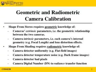
TELIS radiometric calibration Arno de Lange
Planar parallel atmosphere 55 km 50 km 45 km 40 km 45° 30° 35 km Path length ratio 30° / 45° = √2 for all layers
Determining the 0 K line 1 • If you have 2 spectra corresponding to 30° and 45° upwards looking then the ratio of intensity is √2 • From this it follows that: [ y(30°) – y0 ] / [ y(45°) – y0 ] = √2, y0 = [ √2 y(45°) – y(30°) ] / [ √2 – 1 ], where: y(30°) = intensity at 30° y(45°) = intensity at 45° y0 = 0 K line All intensities are in arbitrary units, and most likely in bits from the DACS.
Determining the 0 K line 2 • Two assumptions have been made: • Intensity is linear with path length (= no saturation) • DACS is linear • Note that: • No information of the profile is needed • The 0 K line is determined purely by the geometry of the viewing angles • A hot lot is still needed for the absolute calibration • Horizontal variation is not accounted for. This might be an issue at sunrise with a azimuth viewing angle not along the terminator
Spherical atmosphere 55 km 50 km 45 km 40 km 45° 30° 35 km (Not to scale) Path length ratio 30° / 45° √2 for low layers Path length ratio 30° / 45° 1 for very high layers
Planar vs. spherical • In a planar parallel atmosphere the ratio between two path lengths is fixed and fully determined by geometry • In a spherical atmosphere the ratio between two path lengths changes with altitude: • Flight altitude planar parallel case • Infinite altitude 1 • The main question is how fast does this ratio change with altitude?
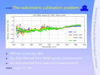
Path length ratio vs. altitudefor a spherical atmosphere and an instrument at 35 km √2
0 K determination • The ratio changes slowly with altitude: • 35 km ratio = √2 • 100 km ratio = 1.39 • The ratio is therefore within 2% of √2 for the whole atmosphere • So, assuming a fixed ratio of √2 gives rise to an error of < 2% in the calibration • The intensity of an OH line at 45° is 12 K • 2% of 12 K = 0.24 K • With two upward looking calibration observations calibration error in zero K level reduced from 12 K down to 0.24 K.
Analysis with synthetic spectra • In the following slides the analysis will be done with synthetic OH spectra • Assumptions made • Spherical atmosphere • Standard tropical atmosphere • Flight altitude of 35 km • LO = 1830 GHz • Single side band (upper side band)
Conclusion • Radiometric calibration can be done by 3 reference measurements: • hot load • deep space at 45° • deep space at 30° • 0 K line can be determined within 0.2 K by this method • Angles of 30° and 45° are not exactly needed, but form a good compromise between: • contrast (factor √2 ) • deviation from geometrical ratio (< 2%)