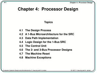
Processor: Datapath and Control
Processor: Datapath and Control. Chapter 5. Processor. Devices. Control. Input. Memory. Datapath. Output. Components of a Computer. Code Stored in Memory. Memory. Processor. Devices. 000000 00000 00101 0001000010000000 000000 00100 00010 0001000000100000


Processor: Datapath and Control
E N D
Presentation Transcript
Processor: Datapath and Control Chapter 5
Processor Devices Control Input Memory Datapath Output Components of a Computer
Code Stored in Memory Memory Processor Devices 000000 00000 00101 0001000010000000 000000 00100 00010 0001000000100000 100011 00010 01111 0000000000000000 100011 00010 10000 0000000000000100 101011 00010 10000 0000000000000000 101011 00010 01111 0000000000000100 000000 11111 00000 0000000000001000 Control Input Datapath Output
Processor Fetches an Instruction Processor fetches an instruction from memory Memory Processor Devices 000000 00000 00101 0001000010000000 000000 00100 00010 0001000000100000 100011 00010 01111 0000000000000000 100011 00010 10000 0000000000000100 101011 00010 10000 0000000000000000 101011 00010 01111 0000000000000100 000000 11111 00000 0000000000001000 Control Input Datapath Output
Control Decodes the Instruction Control decodes the instruction to determine what to execute Processor Devices Control 000000 00100 00010 0001000000100000 Memory Input Datapath Output
Datapath Executes the Instruction Datapath executes the instruction as directed by control Processor Devices Control 000000 00100 00010 0001000000100000 Memory Input Datapath contents Reg #4 ADD contents Reg #2 results put in Reg #2 Output
Fetch Exec Decode What Happens Next? Memory Processor Devices 000000 00000 00101 0001000010000000 000000 00100 00010 0001000000100000 100011 00010 01111 0000000000000000 100011 00010 10000 0000000000000100 101011 00010 10000 0000000000000000 101011 00010 01111 0000000000000100 000000 11111 00000 0000000000001000 Control Input Datapath Output
Output Data Stored in Memory At program completion the data to be output resides in memory Memory Processor Devices Control Input 00000100010100000000000000000000 00000000010011110000000000000100 00000011111000000000000000001000 Datapath Output
Processor • Two main components • Datapath • Control
Design of Processor • Analyze the instruction set architecture • Select the datapath elements each instruction needs • Assemble the datapath • determine the controls required • Assemble the control logic
A Basic MIPS Implementation • will implement the following subset of MIPS core instructions • lw, sw • add, sub, and, or, slt • beq, j
Steps in executing add instruction add $t0, $t1, $t2 • Send PC to memory that contains the code and fetch instruction • PC = PC+4 • Read $t1 and $t2 from register file • Perform $t1 + $t2 • Store result in $t0
Steps in executing lw instruction lw $t0, offset($t1) • Send PC to memory that contains the code and fetch instruction • PC = PC+4 • Read $t1 from register file • Perform $t1 + sign-extend(offset) • Read value at Mem[$t1 + sign-extend(offset)] • Store result in $t0
Steps in executing beq instruction beq $t0, $t1, Label • Send PC to memory that contains the code and fetch instruction • PC = PC+4 • Read $t0 and $t1 from register file • Perform $t0 - $t1 • If result = 0, set PC=Label
Steps in implementing these instructions • Common steps • Send PC to memory that contains the code and fetch the instruction • Set PC = PC+4 • Read one or two registers • Steps dependent on instruction class • Use ALU • Arithmetic/logical instr for operation execution • lw/sw for address calculation • beq for comparison • Update memory or registers • lw/sw read or write to memory • Arithmetic/logical instr write to register • beq updates PC
Components needed for R-format Instructions add $t0, $t1, $t2: $t0= $t1 + $t2 and $t0, $t1, $t2: $t0= $t1 AND $t2
Register File • Consists of a set of 32 registers that can be read and written • Registers built from D flip-flops • has two read ports and one write port • Register number are 5 bit long • To write, you need three inputs: • a register number, the data to write, and a clock (not shown explicitly) that controls the writing into the register • The register content will change on rising clock edge 5 5 5
Portion of datapath for R-format instruction 4 rs rt rd R-format
Components needed for load and store instructions lw $t0, offset($t1): $t0=Mem[$t1 + se(offset)] sw $t0, offset($t1): Mem[$t1 + se(offset)]=$t0
Memory Unit MemRead • MemRead to be asserted to read • MemWrite to be asserted to write • Both MemRead and MemWrite not to be asserted in same clock cycle • Memory is edge triggered for writes Address ReadData Write Data MemWrite
Load/Store instruction datapath lw $t0, offset($t1): $t0=Mem[$t1 + se(offset)] sw $t0, offset($t1): Mem[$t1 + se(offset)]=$t0 4 I-format
Load instruction datapath lw $t0, offset($t1): $t0=Mem[$t1 + se(offset)] 4 rs rt offset I-format
Store instruction datapath sw $t0, offset($t1): Mem[$t1 + se(offset)]=$t0 4 rs rt offset I-format
Branch Instruction Datapath rs rt C If ($rs-$rt)=0, PC=PC+4+(C.4)
Creating a single Datapath Simplest Design: Single Cycle Implementation • Any instruction takes one clock cycle to execute • This means no datapath elements can be used more than once per instruction • But datapath elements can be shared by different instruction flows
4 4
Composite Datapath for R-format and load/store instructions 4 + P C Instruction Memory
Composite datapath for R-format, load/store, and branch instructions
Datapath for for R-format, load/store, and branch instructions ALU Operation 4
Control • We next add the control unit that generates • write signal for each state element • control signals for each multiplexer • ALU control signal • Input to control unit: instruction opcode and function code
Control Unit • Divided into two parts • Main Control Unit • Input: 6-bit opcode • Output: all control signals for Muxes, RegWrite, MemRead, MemWrite and a 2-bit ALUOp signal • ALU Control Unit • Input: 2-bit ALUOp signal generated from Main Control Unit and 6-bit instruction function code • Output: 4-bit ALU control signal
ALU Control Unit • Must describe hardware to compute 4-bit ALU control input given • 2-bit ALUOp signal from Main Control Unit • function code for arithmetic • Describe it using a truth table (can turn into gates):