Download
1 / 40
400 likes | 570 Vues
HL7 Care Plan (CP ) Approach to Developing the Domain Analysis Model (DAM): HL7 Development Framework ( HDF 1.5) (With Discussion Notes in Appendix). André Boudreau (a.boudreau@boroan.ca) Laura Heermann Langford (Laura.Heermann@imail.org) 2011-03-02. HL7 Patient Care Work Group.

E N D
HL7 Care Plan (CP) Approach to Developing the Domain Analysis Model (DAM): HL7 Development Framework (HDF 1.5)(With Discussion Notes in Appendix) André Boudreau (a.boudreau@boroan.ca) Laura Heermann Langford (Laura.Heermann@imail.org) 2011-03-02 HL7 Patient Care Work Group
Approach to Follow • We will follow the Domain Analysis Process (DAP) of the HL7 Development Framework (HDF) • See overview diagram on the next page • See discussion notes in Appendix • We need to familiarize ourselves with the approach • See rest of presentation for a summary of the HDF 1.5 DAP process and techniques • CIC DAM Development Guide HL7 PC 20110104Draft.pptx • Format for use cases, storyboards, activity diagrams and interaction diagrams - HL7Wiki.mht • Examples of DAMs • There are numerous. They tend not to have a solid requirements statement as a starting base.
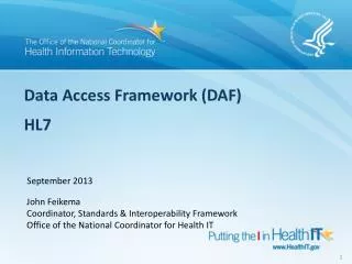
Last updated: 2011-02-09 HDF- Domain Analysis Overview Source: HDF_1.5.doc, page 37
Requirements Document- Structure • Business and clinical context, overall need • Definition of the topic (theme) • Stakeholders and needs • Overall description of processes: contents dynamic, interchange • Interrelationships with other processes • Scope (in and out) • Business objectives and outcomes • Vision Statement
Domain analysis process (DAP) in the HL7 development framework (HDF) Source: HDF 1.5 R1 (Nov. 2009), Section 3- Domain Analysis Process (DAP): Analysis and Requirements Documentation
HDF DAP Contents • Overview • Process • Business context analysis • Use case analysis • Process analysis • Information analysis • Business rules analysis • Quality criteria • Tools • Artefacts
Overview- 1 • Domain Analysis produces a set of artifacts that clearly describe the healthcare business in a given domain in terms familiar to the people who work in that business area. This set of artifacts comprises a Domain Analysis Model (DAM). HL7 workgroups use these artifacts to develop V3 standard specifications. Each artifact in the DAM must be unambiguously stated in a way that can be well understood both by the domain experts and by the HL7 project members who are responsible for developing the specification. • This section presents a set of internally consistent processes and techniques for analyzing and documenting interoperability requirements. It allows domain experts to document requirements explicitly in a manner consistent with HL7 design. These processes make extensive use of the UML 2.1 standard notation and tooling (see sections 3.6 and 3.7). The process encourages project teams to focus on the underlying healthcare information and process requirements before designing a standard. While the focus of this chapter is to identify interoperability requirements for standard development, this process could be used to analyze requirements for other purposes or projects.
Overview- 2 • Requirement/Domain Analysis is a task typically performed by domain experts and business analysts who represent the users and understand their system interoperability needs. The problem space for HL7 is defined by the interoperability requirements of stakeholders in a given domain of healthcare delivery or administration. This includes all sharing of information among healthcare stakeholders that may be required for the collection, aggregation, reporting, and other analysis of clinical, administrative, and financial data information that pertains to the business. • A DAM defines what needs to be done, not how to do it. It is important to separate the description of requirements from the design of the solution. Prematurely including technical and implementation details will compromise the clarity of the original problem and will result in standards that fall short of the business needs. The DAM is used to create standard specifications by harmonizing it with HL7 references including the Reference Information Model (RIM), structural vocabulary, and application roles.
HDF- Domain Analysis Overview Source: HDF_1.5.doc, page 37
3.4.1 Business Context Analysis • The first sub-process in the Requirements Documentation process analyzes specific issues or requirements in the context of the healthcare business process that is to be improved either by developing new software or through HL7-based interoperability. • This is accomplished using one or more storyboards. A storyboard is a narrative that describes a representative scenario that illustrates the problem or requirement as well as identifying the interchange of information and the various actors involved. • The purpose of this sub-process is to capture the domain experts’ knowledge in a simple fashion and to document the business context for message exchange. The analysis of the business context is intended to identify a typical scenario (or storyboard) that describes the process intended for automation using the standard developed by the project.
3.4.2 Use Case Analysis - 1 • Use Case Analysis is used to identify the integration scenarios a project or artifact is intended to support. • The Use Case Model formally identifies the actors and use cases illustrated in the storyboards and associates the actors with the use cases they participate in. It enables the project or committee to clearly identify the functional areas the system will cover and the actors involved. A Use Case Model may consist of multiple use cases and multiple actors. • Each use case provides one or more scenarios that convey how the system should interact with the end user or another system to achieve a specific business goal. Use cases typically avoid technical jargon, preferring instead the language of the end user or domain expert. • Each use case focuses on describing how to achieve a single business goal or task. Actors are parties outside the system that interact with the system. An actor can be a class of users, roles users can play, or other systems. • Use cases treat the system as a "black box" and interactions with the system, including system responses, are perceived from outside the system. This policy is deliberate because it simplifies the description of requirements and avoids the trap of making assumptions about how the functionality will be implemented.
3.4.2 Use Case Analysis - 2 • A use case identifies: • Actors participating in the use case • Pre-conditions • Flow of events • Post-conditions • Derived events/interactions • Activity, Sequence, and/or State diagrams can be used to further elaborate the use case analysis.
Analyze Use Cases The purpose of the following diagram is to describe the process used to identify the actors and use cases in a formalized structure that enables Domain Experts and Business Requirements Analysts to identify the functional interoperability scenarios. Document Actors' Actions: Analyze the storyboards to identify the systems, business actors, and functions/actions performed. Describe interoperability use cases: Describe the conditions under which information is exchanged and the responsibilities of each actor based on information received.
Additional Guidance • Consider writing use case text only for those cases whose steps include interoperability to keep the analysis manageable. • Create the use case model with respect to the system that initiates the information exchange. The system that receives the message of interest is a secondary actor in the use case. • After writing the use case text, include one or more scenarios. • Create scenarios for the use case messaging success and failure conditions if there are any and they affect the contents of the message. A use case scenario illustrates a single instance of the flow through a use case. It typically does not include any options. You may rely on additional scenario to describe various options.
3.4.3 Process Analysis • The process flow shows the information exchange necessary for automation of a healthcare business process. In UML, Activity Diagrams are used to visualize the activities and flow of a healthcare business process as described by use cases. Each Activity Diagram may be represented using a Process Flow - see section "3.7 Artifacts, Process Flow" for details. • The purpose of this sub-process is to document how a project or committee may capture the behavior described in the business process in a structured notation (UML) using UML tools.
Analyze Process Flow Refine the steps in the use case model: Clarify and expand the storyboard into an Activity Diagram. The Activity Diagram will visualize the activities and flow of a healthcare business process. The facilitator will use UML to document these process steps. Document Information Exchange: The process flow is broken into steps and then the message exchange is clearly illustrated. Special care will be paid to message processing rules and to identifying the business triggers. Review may require several iterations
3.4.4 Information Analysis • One of the most important aspects of requirements analysis is the development of a clear understanding of the business objects of interest, their associations, and their attributes. The purpose of this sub-process is to document the information shared between systems in order to support healthcare business processes. UML class diagrams are used to describe the information required to appear in messages. Documentation of the structure of a particular business process is done using a combination of an information model, represented as a UML Class Diagram, and a carefully written glossary of the terms used by domain experts to define the static elements within that process.
Analyze Information Exchanged The information model and its associated diagrams document the static syntactic and semantic relationships of importance in the healthcare business process including the responsible parties/entities and the various data elements/structures required by the process. The semantic meaning of each item and attribute in the information model is described in the model documentation. The following diagram describes the steps required to develop the information analysis artifacts. See next page
Analyze Information Exchanged • Analyze Information Shared • Document and specify the information payloads of interest: • For each exchange of data identified in the activity diagram, determine the data elements required. • For each data element include a complete definition that is not self-referential and includes examples, where appropriate. • Apply a consistent style guide. This includes naming conventions for class, attribute and association names (e.g. Upper Camel Case. Lower Camel Case, etc). • Analyze value sets • The local value sets, code systems, and code sets are identified and documented as enumerations in the UML model (each literal corresponding to a code). If any external code sets are used, they will be named explicitly in the information model. If any external code systems are used, they will be named explicitly in the information model. Each new vocabulary term must use ”definition” syntax that is not self-referential with examples, etc.
3.4.5 Business Rules Analysis • The main purpose of this process is to describe how a committee or project should document additional business rules that are important in creating the message specifications such as business triggers for messages. This structure is added to the Activity Diagram using the "object/instance" iconography (in the case of HL7 Specifications, most objects that are exchanged are data objects that have no inherent behavior). An analysis of the business rules produces important information to describe any events that trigger the exchange of information.
Describe the business rules and triggers Analyze state transitions for business objects: Analyze the data exchange requirements that appear as Data Objects in the Activity Diagrams. Document the life cycle of each of these data objects in UML State Diagrams. Analyze other business rules: Analyze the Story Boards and Activity Diagrams to determine Business Rules and conditions that are not adequately captured in the Domain Analysis Model, Domain Glossary and State Chart. A complete DAM will include a thorough analysis of business rules governing the processing and exchanging information in order to meet interoperability requirements.
Describe the business rules and triggers • Additional guidance • Given that the information model, class and attribute glossary, and state charts may overlap when documenting the business rules, there is no need to document those business rules in the rules analysis. • As a guiding principle, analysis should focus on those business rules that will be important to the interoperability as specified by the business use cases. • Business rules may be written in an informal style or in a consistent formalized style. It is advisable to begin capturing business rules in an informal style. A more formal style can be created later, if needed.
3.5 Quality Criteria (requirement specifications) • Requirements specifications must be complete, correct, unambiguous, deterministic, testable, verifiable, traceable, and internally consistent. • If complete, a requirements specification must specify all information needed to develop the static and dynamic logical and implementation models. It should not include unnecessary information. It must provide the detail necessary to develop the HL7 model specification. For example, a requirements specification “send prescription data to the pharmacy” is not complete. It does not address questions such as “What is the prescription data?” or “What is the pharmacy supposed to do with it?” • If correct, the requirements specification must correctly specify the conditions and limitations that will be encountered in building the model. Building on the earlier pharmacy example, how should the model behave if the prescribed medication is not available in the pharmacy? • An unambiguous requirements specification leaves no room for doubt. Data that is exchanged or stored needs to be clearly defined. Message elements that are not well defined inevitably lead to interoperability issues. • A testable requirements specification is one where each requirement can be examined once the HL7 model is complete to determine if the model does indeed fulfill the requirement. As such, requirements need to be specified in an objective fashion. Using UML to represent the requirements for the static and dynamic models helps eliminate issues like these. • A requirements specification is consistent as one examines the transitions from lesser to greater detail. • A traceable requirement is one that can be traced backwards and forward through the requirements documentation process. • Requirements must be internally consistent. One requirement must not conflict with another.
3.6 Tools • A UML 2.1 tool may be used to analyze the integration requirements that are intended to be met by standard specifications and supports the creation of DAM artifacts outlined in section 3.7. HL7 recommends the use of Eclipse-based UML 2.1 tools that can be extended easily using open-source plug-ins and features.
Domain Analysis Model (DAM) • A Domain Analysis Model is an analysis model that describes business processes, use cases, process flows, business triggers, and the information exchanged that are derived from a project's requirements. A sample domain analysis model is available in Annex A. • A DAM is equivalent to a Requirements Analysis Specification but instead introduces a consistent notation (UML 2) and style in place of narrative analysis information. Domain analysis is a well-established discipline in software development that is intended to improve the way in which requirements are related to SMEs, analysts, and integration solution implementers. The artifacts described here adapt the best-practices established in software development to the development of healthcare standards. Having well-documented and thoroughly analyzed requirements of standard design specifications will better prepare HL7 work groups to respond to ballot comments and questions.
Domain Analysis References • Carnegie-Mellon University has developed its own analysis methodology known as "Feature-Oriented Domain Analysis" that has been applied widely in public/federal and private industry projects. Please refer to the following for more information: • Kayo C. Kiang, Shalom G. Cohen, James A. Novak, William E. Hess, and A. Spencer Peterson, "Feature Oriented Domain Analysis (FODA) Feasibility Study", CMU/SEI-90-TR-21, Software Engineering Institute, Pittsburgh, PA, November, 1990 • http://www.sei.cmu.edu/domain-engineering/domain_anal.html • http://www.sei.cmu.edu/str/descriptions/foda.html • http://www.sei.cmu.edu/str/descriptions/deda.html • Though based on generic domain analysis, the focus of the HDF-based methodology is in specifying how we in healthcare interoperability use DAMs for standard development. It is important to mention that a DAM contains not only an information model but also a comprehensive analysis model which includes business processes and system interactions. The behavioral/dynamic aspect of a DAM is often overlooked by HL7 standard developers.
Use Case Analysis Model • The Use Case Analysis describes typical scenarios of end-users interacting with systems for the purposes of sharing or looking up information. In HL7, the Use Case Analysis is a documented as a UML model or package in the DAM that describes a interoperability requirements in terms of use cases. It consists of all the actors of the systems involved in interoperability and all the various use cases by which the actor interact with the system, thereby describing the functional and integration behavior of the systems involved. • Use case models specify actors and use cases: • 1. Actors: An actor is a person who will use the system we are designing. A bank customer interacting with the software of an automated teller machine is an actor. An astronomer inputting the coordinates of a star to a telescope aiming program is an actor. A bookstore clerk checking the computer to see if a particular book is available is an actor. Usually an actor initiates some operation, although sometimes the actor may act in other ways, such as receiving information or assisting in an operation. • In a large project, just identifying all the actors may be difficult. The designer needs to look for people or other systems that: • Provide information to the system • Need information from the system • Assist other actors • 2. Use Cases: A use case is a specific task, usually initiated by an actor. It describes a single goal the actor wants to attain. Examples are the applying for driver's license, renewing a driver's license, etc. A detailed example of use case analysis is provided in Annex A.
Storyboard • A storyboard is a narrative description of a series of steps involving some exchange of information between different participants to achieve the objectives of a healthcare business process. The list of steps can be in generalized, abstract terms, or in the form of a real-world example. A storyboard illustrates the basic path, simple path, alternate, or error path of information and its content is comprised primarily from guidance by the domain experts. • Storyboards should be written using business terminology to illustrate the context for the message exchange, functional model, etc. • The content of the initial storyboards should be representative of normal business processes. Avoid exception cases. Attempting to document all exception cases in a business process can be an exhaustive task that diverts focus from the typical case, particularly at this early stage of the requirements process. • A storyboard may be imprecise or incomplete in its initial draft. It should be revised over time if changes/updates are deemed important. It typically has no branching or decision points. The information in a storyboard will typically be made more precise when the corresponding Activity Diagram is created. • The storyboard may include examples (e.g. names of people, organizations, systems, and data values) as appropriate. This helps make storyboards illustrative of the real work and also to make clear that items of interest may be of different types than assumed (e.g. that a patient in some cases may be an animal, that a guarantor may be an organization, etc). • Avoid the use of acronyms, abbreviations, etc., because the intended audience is a diverse group, some of whom would likely be confused. If these constructs are deemed important for the intended audience, they can be included in parentheses after the term. For example, Department of Motor Vehicles (DM).
Glossary of Business Terms -1 • The Glossary focuses on the business objects of interest and their attributes. Some of the concepts in the glossary may also appear as classes or attributes in the information model: • The Glossary uses business-specific names and references with unambiguous definitions provided by the SMEs and analysts. • Element definitions must be understood by the SMEs and any end users. • To jump-start the modeling process, it's sometimes helpful to think of the events, the relevant parties (persons and organization), places, and items that participate or are used in those events, and how they participate in those events. Consider as well any "catalogs" of events and items. • The objects that appear in the activity diagram are a primary source for this analysis artifact. • Some data objects will have been identified in the business requirements.
Glossary of Business Terms -2 • It is generally most beneficial to go for breadth first and depth later. Therefore, capture the classes and only enough attributes to distinguish them before attempting to identify all the attributes. Similarly, capture only the relationships between classes before attempting to document their cardinality (“can there be more than one?”) and optionality (“must there be one?”). • Make the model just "good enough". Avoid the temptation to perfect it or make it exhaustive. Don't get attached to this model. As the iterative process progresses you'll learn more information and later models will improve. • While most models benefit from the use of conventions, do not invent conventions to the detriment of creating the model. Annex F provides naming conventions to start with. • Whenever possible, use the features of the UML modeling tool to create the Domain Glossary. • UML modeling tools can generate a document of the class and attribute definitions to auto-generate the glossary publication. • Review definitions from glossaries of other standards development organizations, industry consortium, dictionaries, etc. whenever feasible. HL7 encourages collaboration with these third-party organizations and respects their intellectual property. Always reference the original source in the definition.
Information Model (Analysis) • The UML-based information model contains classes, attributes, associations, and packages required to describe the information shared by systems in order to support the business requirements for a standard specification. Local value sets may be expressed as classes called enumerations and assigned to coded attributes. • The information model is not the actual specification of payload structures as it does not include the order of the data items in the message, the exact formats of the individual data items, the exact location of the data items within the message, and it might not include the exact data types of the data items in the message. Rather, it’s an analysis of the information required to support the underlying requirements expressed in a way in which SMEs can relate to the information, semantics, and structure. • This model is not an HL7 static/information model but instead an element of the DAM. It describes the information exchanged to support a project's requirements (for a project intended to produce interoperability standards).
Business Trigger Analysis • This analysis artifact documents the allowed states and transitions that correspond to message triggers. The "state change" triggers are similar to trigger events defined in HL7 specifications, but they relate to events in the "real world". While HL7 has pre-defined a set of states and transitions, the targeted business area may require different levels of granularity. • These states and transitions will eventually be mapped or related to HL7 reference states and transitions for each type of Reference Information Model (RIM) class (e.g. Act, Managed Participation, Role, and Entity). • When analyzing the state events for an object, candidate states in a state chart diagram for an event could be active, completed, suspended, or terminated. • Typically, the activities for DAM creation and creation of a comprehensive Activity Diagram "feed" each other. They may be performed in parallel, by switching back and forth between one and the other, or some other combination.
Process Flow • The process flow represents a dynamic view of end-user and system interactions and is often the best way to represent the interactions between systems, derive the application roles, and trigger events. Process flows rely on UML Activity and/or Sequence Diagrams to represent the sequence of user-to-system and system-to-system actions required for specific business processes. • An Activity Diagram identifies a sequence of steps and the information that is transferred from one participating role/actor to another. Sometimes called a "Swim-Lane Diagram", the diagram represents the flow of control and helps identify when information is required to be transmitted to achieve the objectives of the storyboard. These diagrams use UML 2.x notation to represent actions, activities, decisions, control, and information flows between users and systems. An activity diagram is also a variation of state machine in which the states represent the performance of actions or sub-activities, and the transitions are triggered by the completion of the actions or sub-activities. Therefore, it represents the state machine of a procedure itself. • A Sequence Diagram is used to represent the flow of messages, events and actions between the systems or components of a system. Time is represented in the vertical direction while the sequence of interactions of the header elements are displayed horizontally. Sequence diagrams are used primarily to document and validate the architecture, interfaces, and logic of various system scenarios by describing their action sequences. Sequence diagrams provide a dynamic view of the system behavior which can be difficult to extract from static diagrams or specifications. Although sequence diagrams are typically used to describe object-oriented software systems, they are also extremely useful as system architecture engineering tools, as process flow diagrams in business process engineering, and as message sequence charts and call flows for system design and analysis.
Business Rules Description • Business rules may be described using a variety of dynamic views (business process diagrams, activity diagrams), narrative text, or constraint language statements (e.g. OCL) based on the DAM. These business rules may be used to apply additional constraints to the information exchanged or processing rules. • The bullet items below describe sample business rules using natural language: • At any point in time, a person can hold a driver’s license (active or suspended) in only one state. • In order to obtain or renew a driver’s license, a person must have no moving motor vehicle violations in the past three years. • In order to obtain or renew a driver’s license, a person must have no health issues that would adversely affect their ability to operate a motor vehicle. • The Department of Motor Vehicles accepts the following payment methods - cash, check with acceptable picture ID, or MasterCard/Visa credit/debit cards.
Last updated: 2011-02-09 Notes from Jay Lile – 2011-02-03 • INFORMATION: The DAM should inform a constrained model (DIM/DMIM/RMIM), which is then used as the basis for specifications (CDA, message, etc.). If we build a DAM, we'll presumably use it to update the Care Provision DIM. The updated DIM should be in the list of balloted deliverables. (This is much clearer in PSS 4d, but the sections should be in harmony.) • SCOPE ISSUE: We will also need to determine whether the DAM scope should be restricted to the care plan or should reverse-engineer the entire Care Provision DIM. • PSS (Project Scope Statement) UPDATE: The Scope section (4a) discusses semantic scope, but it does not lay out the scope of work. I'd suggest that the text currently in 2a be removed from 2a, expanded, and added to 4a. • GUIDELINE: The term "DSTU" is being used to refer to deliverables. I find that confusing: DSTU is a status, not an artifact. It would be clearer to me if artifacts were referred to as messages, cda documents, DAMs, and DIMs, and ballot status were used to modify those artifacts. E.g., "the purpose of this project is to develop a Care Plan CDA document, with all necessary antecedent artifacts [list them], and to ballot this document as DSTU." • DELIVERABLES: Modeling the information space will almost certainly be useful, but I'm still in the dark about the use cases. Under what circumstances is it necessary to communicate a care plan? For what business purpose are organizations paying their employees to volunteer and develop this standard? • PSS UPDATE: External collaboration (6) could use more detail. That would also make it less necessary to mention this slightly distracting information in previous sections.
Last updated: 2011-02-16 Lloyd Mackenzie: Observations on DAMs -1 • Presently, a DAM is not something well defined in HL7. It is not a single artefact but a variable collection of artefacts: functional requirements, use cases, behavioural models, activity diagrams, interaction diagrams, etc. • There are 3 levels of design: conceptual, logical and implementable. The DAM is at the conceptual level • For the conceptual level: • Capturing requirements is key • Requirements must be intuitive to the user community and verifiable • This level is more detailed that the logical level • It must be well bounded because conceptual models tend to be large • The conceptual information model • The challenge is arriving at a language and set of well defined concepts accepted by the broad community of stakeholders/ clinicians • Definitions are critical: include usage notes, examples and aliases • Note: ISO Continuity of care concepts (NWIP being balloted to merge the 2 parts) could be one key input to speed things up • The model must be mapped and validated against the RIM to ensure completeness
Last updated: 2011-02-16 Lloyd Mackenzie: Observations on DAMs -2 • We need to decide which artefacts we will produce • HL7 does not have a formal set of tools nor predetermined publication format • We need to speak to the Publications WG early in the process to ensure that what is prepared can be handled for ballot • For the models, 2 major options • Concept maps (e.g. mind maps): easy for clinicians to understand, less technical looking • UML diagram: they are more precise, with cardinalities; can be ‘scary’ for non technical folks; could come after the concept maps • Datatype: do we want to specify? If so, which ones? R2? They are very technical and could be added at a later point. • Key: decide on core objective: capture requirements and validate with user community • Find ways to make this easier