Download
1 / 46
470 likes | 722 Vues
Next year’s Aircraft Design class: We will (again) have a joint team with ME to build and fly a morphing airplane Send me email: whmason@vt.edu to apply We will have 4 AEs on this team Undergraduate research:

E N D
Next year’s Aircraft Design class: We will (again) have a joint team with ME to build and fly a morphing airplane Send me email: whmason@vt.edu to apply We will have 4 AEs on this team Undergraduate research: - lots of opportunities to help the design class software and do student AIAA papers, see me if you are interested. Announcements/Opportunities
AOE 3054Aerospace and Ocean EngineeringInstrumentation and LaboratoryA LectureonAerodynamic TestingW.H. Mason
• Where you test • Why you test • How you test • Some specifics for your lab Overview
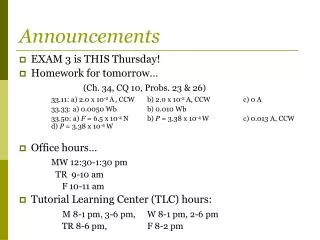
The NTF at NASA LangleyHampton, VA Feb. 1982 Performance: M = 0.2 to 1.20 PT = 1 to 9 atm TT = 77° to 350° Kelvin
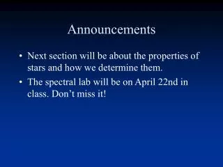
The Full Scale Tunnel at NASA Ames 40x80 Foot Test Section 80x120 Foot Test Section Aviation Week & Space Technology, Dec. 7, 1987
• Lot's of introductory material on Aero Test in the manual: read it! • The standard reference book: Barlow, Rae and Pope, Low Speed Wind Tunnel Testing Information Sources
Preparation and planning are required to get into any tunnel: • Make pre-test estimates • Prepare a pre-test report including a Run Schedule Wind Tunnel Testing is Expensive
Safety, accidents can happen Pretest Planning - the key to success Model Design The Run schedule Typical Tests: - force and moment both performance, stability, and control - pressure distributions - flow diagnostics on and off surface flow visualization Key Items
Research Fighter Configuration (RFC)Visualization with a Tuft Grid Small Model in Grumman Tunnel
Another Way To Do Flow Diagnostics Kurt Chankaya, Grumman (now Lockheed)
Typical way to put tufts on the wing From Pope and Harper’s text, taken in the Wichita State tunnel
Oil Flows for Surface Visualization 1 SC3 Wing, M = 1.62, a = 8° (nominally attached)
Oil Flows for Surface Visualization 2 SC3 Wing, M = 1.62, a = 12° (TE flow separation)
Laser Light Sheet example Light Sheet from an argon laser, the flow is seeded with an standard smoke generator. Northrop IR & D example of vortex flow over a delta wing configuration. Exhibited at the 36th Paris air show. Aviation Week & Space Technology, July 29, 1985
Accuracy important! - drag, under all conditions - low speed near max lift - transonic cruise condition Model Fabrication:
WT model with high LE accuracy Req’ts. Supercritical Conical Camber (SC3) Wing, developed using CFD. The leading edge contour accuracy is critical. Note the arc of the wing along the trailing edge, a sort of “gull shape”
• Fundamental: Mach number and Reynolds number - Match Mach, do your best on Reynolds, leads to: - transition fixing • Test issues: - wall interference, flow angularity, nonuniformity • Adjustment from model scale to full scale Simulation Issues
• A high quality flowfield - uniform mean flow - low turbulence level - low flow angularity • came from NASA in 1958 • 6'x6' test section, 24 ' long • 600 hp motor/14' fan • 275 fps max speed The Virginia Tech Stability Tunnel
Tension change in wire changes resistance You used one before? • Assume that the balance is adequately calibrated - we will not check it this year Use a Strain Gage Force Balanceto Measure Loads
• two weeks • 1st week - get ready - check out tunnel, make pretest estimates • 2nd week: test! - run the model Mechanics for this lab:
The Tests! New this year: we have 2 possibilities: 1. The “standard” rectangular wing 2. The Pelikan Tail (from a senior design project) Your choice!
Use Experimental techniques to find aero characteristics of: 1. A rectangular, unswept wing • with and w/o transition strips or 2. A novel tail concept almost used on the Boeing JSF, and subsequently adopted by our senior UCAV-N team Objective:
The Rectangular Wing Model The airfoil: originally a Clark Y, recently modified (thickened) to strengthen the model - How does this change the test estimates?
The Pelikan Tail = HINGE LINE
Why should you do this? Let those seniors talk?