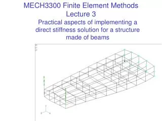
MECH3300 Finite element Methods
MECH3300 Finite element Methods. LECTURE 2 - Commercial packages and how they work. Commercial finite element packages . History - initially punched card input and printer output. The original codes are now the “solver”, but have graphical preprocessing and post-processing added.

MECH3300 Finite element Methods
E N D
Presentation Transcript
MECH3300 Finite element Methods LECTURE 2 - Commercial packages and how they work
Commercial finite element packages • History - initially punched card input and printer output. • The original codes are now the “solver”, but have graphical preprocessing and post-processing added. • Geometry can be imported from CAD packages - a standard format such as IGES may be needed for this. However CAD geometry is often unsuitable for analysis, as additional geometric approximations must be made. More later … • Appropriate geometry can also be constructed within the finite element preprocessor (a specialized CAD package). • This typically involves creation of geometry (points, lines, surfaces and solids), then “meshing” - creating the actual finite element model (nodes, elements, restraints, loads, properties etc). • For analysis of machine components, a finite element package can be embedded within a solid modeling CAD package, to automatically mesh CAD solids. This is easy to use, but has limitations ...
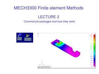
Typical output from a finite element package Output can be displayed as scaled deflected shapes, contour plots of stress, animation of deformation, xy plots etc.
Linear v nonlinear analysis • For elastic behaviour and small deflections stress strain and force deflection. The result for static analysis is a set of linear equations F=[K]u which can be set up and solved once. • However, if non-linearities are present, an iterative solution is needed, involving a series of linear approximations. This may involve 100’s of updates to correct for • finite deformation causing shape change (load not deflection), • plastic deformation (stress not strain), creep or • finite sliding in contact or loss of contact (stiffness changes) etc. • Hence nonlinear analysis is much less efficient, and it may not converge to a solution at all. • Most commercial packages have severe limitations when applied to nonlinear problems.
Examples of commercial packages • STRAND7 - Australian package mainly for linear structural analysis - good for beam models - will import solid models but cannot generate its own solid geometry. • NASTRAN for Windows - mainly for linear structural analysis - can generate its own solid CAD model. • ABAQUS - written for nonlinear analysis of structures (nonlinearities include finite deformation, plastic deformation, sliding contact, loss of contact etc.) • ANSYS - A versatile package that includes capabilities for other field problems (eg electric and magnetic fields). • LS-DYNA - a package for short duration dynamics such as impacts - used to simulate car smashes etc. • COSMOS - mainly for linear structural analysis, including structural optimization. Available embedded in Solid Works. • ADINA - can model fluid-structure interaction, metal forming etc. • All these have some capability to solve dynamics problems.
Researchers • Commercial codes are often developed from research codes • NASTRAN was written for NASA at Univ. of Georgia. It has been commercialised several times, most successfully by MSC Software. • DYNA was written by Dr Hallquist and colleagues at University of California, Lawerence Livermore doing military-funded research. • STRAND started as code developed at Univ. of Sydney and Univ. of NSW. Researchers continue to push the limits of what problems can be solved. Eg at Northwestern University, Professor Belytschko has recently been growing cracks through finite element meshes.
Demonstration versions • Most commercial packages have demonstration versions that are crippled in various ways to prevent commercial use (eg node limits apply). • STRAND7 demo: available as a .zip file at www.strand7.net.au • It refuses to save a model, but results can be printed. • ABAQUS is available in a 1000 node student version for US$89 with 5% discount for 10, 10% discount for 20 etc. http://www.worleyparsons.com • 50 can be obtained for AUD$97 each including postage. • NASTRAN for Windows demo:available on CD. It will save models and save results. It requires a 3 month license authorization file to be downloaded by sending an email from the machine on which Nastran is installed, to n4w.license@mscsoftware.com • The reply to this message is a file license.dat, which must be placed in the …/solver/conf folder created when Nastran is installed. You need to check that the .rcf file in this folder contains the line $auth=c:\mscvn4~1\solver\conf\license.dat
What do solvers do? What happens when you press the “solve” option on a menu…. SUBTOPICS 1. THE DIRECT STIFFNESS METHOD 2. ASSEMBLY OF ELEMENT MATRICES 3. DEGREES OF FREEDOM IN A STRUCTURE 4. RESTRAINTS [or constraints or freedom conditions] 5. THE SOLUTION PROCESS
The direct stiffness method Most structures are statically indeterminate, so that loads are shared between members in accordance with their stiffness. Hence we can’t just use statics. The direct stiffness method refers to writing a large stiffness matrix to describe a structure. It was invented as a method of hand calculation, but only became popular once computers could solve the equations. Structural equations can be written as displacement = f(loads) giving “compliance” or “flexibility” terms or as loads = f(displacements) giving stiffness terms. The advantage of the latter is that it leads to a sparse stiffness matrix, with non-zero terms only where local interactions between members or elements occur.
Assembly of element matrices • Imagine expanding each element matrix with rows/columns of zeroes so that it refers to all displacements at nodes and all forces at nodes, giving [Ke1], [Ke2] etc.. • Forces on element 1 are, F1 = [Ke1]u where u is the full displacement vector. F1is a column vector of the same size as u but with zeroes corresponding to nodes not on element 1. • Similarly for element 2, F2 = [Ke2]u etc. • Adding forces at nodes F= {[Ke1] + [Ke2] + …}u = [K]u • This is a special type of addition called assembly, as the element matrices are expanded to full size before being added.
Example of assembly- 2 springs in series Let spring 1 have axial displacements u1 at node 1 and u2at node 2. It’s element equations are Ie the force in the spring is its stiffness k times the difference in displacement over its length. To add another spring in series, add another node with F3and u3associated with it. The equations for spring 1 are now u1 u2 u3 k k Spring 1 Spring 2
Example of assembly - 2 For the second spring, its expanded stiffness matrix is that in the eqns. Adding the forces at nodes Hence the assembled stiffness matrix is Note this summation assumes at all elements at a node have the same displacement - for beams and plates rotations are matched as well, so this means a joint is always treated as a rigid joint by default, not as a pin joint.
A row of springs in series The process of expanding element matrices with zeroes and adding them can be continued. For instance, for 5 equal springs end to end, [K] is Note this matrix is banded - the non-zero terms cluster around the diagonal and it is symmetric. These properties typically apply to matrices of structural problems and are exploited in equation solvers.
Degrees of freedom • Each movement that can occur independently is a degree of freedom. The total number of degrees of freedom is the number of equations that must be solved and the size of [K]. • For beam or plate models there are potentially 6 degrees of freedom per node. • For solid models there are potentially 3 degrees of freedom per node, as no rotations are used to describe the deformation. • The number of degrees of freedom is reduced by applying restraints or constraints, that stop certain displacements. • At least 6 restraints must be present in 3D to prevent 6 possible rigid body modes of deformation, as there is no unique solution to the displacements of an unrestrained structure.
Restraints (or constraints) • The effect of fixing displacement component number i is to remove row i and column i from the stiffness matrix describing a structure. • The row is removed as it contains coefficients of a redundant equation for an unknown reaction to the constraint. • The column is removed as its terms are multiplied by zero. • The effect of these changes is to maintain a symmetric stiffness matrix. • 3 by 3 example - next slide.
3 by 3 example of applying a restraint Consider the 3 by 3 set of equations below If u2= 0 then column 2 of [K] is multiplied by zero, and F2becomes an unknown reaction. Hence we can solve for u1and u3by solving Having found u1and u3we can then find F2 = k2 u1 + k5 u3 if the reaction is of interest. Finding a reaction may need to be done to check that the reaction is zero, in a case where the restraint is an artificial one, applied just to stop rigid body motion.
The solution process 1.Find element stiffness matrix for each member, linking forces/moments to displacements/rotations at joints. Write these in the global coordinate system. 2. Add (or assemble) these to give a large matrix [K], by expanding each member matrix with rows/columns of zeroes. 3. Remove rows and columns of [K] corresponding to any constrained displacements or rotations. This must be done to at least prevent any rigid body motion or mechanism. 4. Solve [K] u = F for joint displacements or rotations u. 5. Use each element matrix times relevant displacements to find the forces/moments on nodes of that element. These imply internal loadings (eg bending moment), and internal loadings enable stresses to be found.
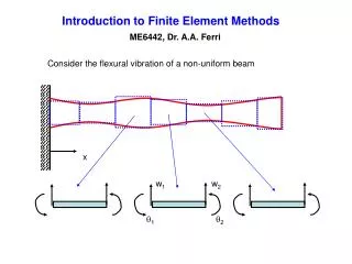
Results for a beam model A beam element loaded at each end only will have linear variation of bending moment over its length in each principal plane. Gravity or inertia loading can give a uniform distributed loading. This leads to quadratic variations of bending moment. The sign of a moment at a node may be different to that of the bending moment in the beam there. Results must be reported in local axes, aligned with the principal axes of a beam, not in the global axes used to describe the whole model, in order to distinguish loading causing bending from that causing twisting or axial loading. Bending moment Local axis directions are determined by the reference node position.