Download
1 / 23
280 likes | 588 Vues
Introduction to Finite Element Methods. ME6442, Dr. A.A. Ferri. Consider the flexural vibration of a non-uniform beam. x. w 1. w 2. q 1. q 2. Within each element, we have a particular E, I, r , A, L. w 1. w 2. q 1. q 2. x.

E N D
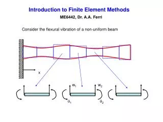
Introduction to Finite Element Methods ME6442, Dr. A.A. Ferri Consider the flexural vibration of a non-uniform beam x w1 w2 q1 q2
Within each element, we have a particular E, I, r, A, L w1 w2 q1 q2 x Assume a cubic displacement field (exact for statics.) Need to relate the 4 generalized coordinates for each element to the displacement field within each element At element endpoints:
In matrix form, Solve for {a} Displacement field becomes: Shape or interpolation functions
N1(x) N3(x) 1 1 N2(x) N4(x) 1 1 (Hermite Polynomials)
Element potential energy q4 q3 q2 q1 With this substitution, we get where
Since polynomials are easy to integrate, we can obtain the “elemental stiffness matrix” in closed form: defining The potential energy for each element has the form
Element kinetic energy . . . . q4 q3 q2 q1 With this substitution, we get where
As before, we can obtain the “elemental mass matrix” in closed form: defining The kinetic energy for each element has the form
We can also consider a distributed force per unit length on each element f(x,t) w1 w2 q1 q2 x Elemental virtual work can be expressed as where
The potential energy of the entire system is the sum of the contributions from each element Define Total potential energy can be written Similarly, and
(4p)x(4p) “Block-diagonal” Similarly, we can construct an “unassembled” mass matrix and forcing vector (4p)x(4p) (4p)x1
In this “unassembled” form, many of the q’s are redundant. Thus, we cannot just substitute Ttotal, Vtotal, and Qtotal into Lagrange’s equations. For example etc w1 w2 w3 w4 q2 q3 q4 q1
Write constraints in the form of a “connectivity” or “compatibility” matrix [b] (4p)x(2p+2) or (more rows than columns)
“Global” stiffness matrix “Global” mass matrix “Global” force vector
The last thing that must be considered are geometric constraints. For example, w1 w2 w3 w4 q2 q3 q4 q1 Set these to zero This is easily accomplished by deleting the corresponding rows and columns of the global mass matrix, stiffness matrix, damping matrix (if present), and force vector
Numerical Example– Steel beam, 3 elements w1 w2 w3 w4 q2 q3 q4 q1 E=2e11; rho=7800; L=1; A=0.02*0.004; I=0.02*(0.004^3)/12; ke=element_stiffness_matrix(E,I,L/3); me=element_mass_matrix(rho,A,L/3); (Assume that beam is uniform. If not the case, we would call element_stiffness_matrix and element_mass_matrix 3 times, using different E, I, r, A, L values.)
Elemental Stiffness Matrix function ke = element_stiffness_matrix(E,I,L); ke = [ 12 6*L -12 6*L ; 6*L 4*L^2 -6*L 2*L^2 ; -12 -6*L 12 -6*L ; 6*L 2*L^2 -6*L 4*L^2]; ke = ke*E*I/L^3; generic Matlab function for 4 DOF beam element ke = 1.0e+003 * 6.9120 1.1520 -6.9120 1.1520 1.1520 0.2560 -1.1520 0.1280 -6.9120 -1.1520 6.9120 -1.1520 1.1520 0.1280 -1.1520 0.2560
Elemental Mass Matrix function me = element_mass_matrix(rho,A,L); me = [ 156 22*L 54 -13*L ; 22*L 4*L^2 13*L -3*L^2 ; 54 13*L 156 -22*L ; -13*L -3*L^2 -22*L 4*L^2] ; me = me*rho*A*L/420; me = 0.0773 0.0036 0.0267 -0.0021 0.0036 0.0002 0.0021 -0.0002 0.0267 0.0021 0.0773 -0.0036 -0.0021 -0.0002 -0.0036 0.0002
K_tot = zeros(12,12); M_tot = K_tot; K_tot(1:4,1:4)=ke; K_tot(5:8,5:8)=ke; K_tot(9:12,9:12)=ke; M_tot(1:4,1:4)=me; M_tot(5:8,5:8)=me; M_tot(9:12,9:12)=me; beta=zeros(12,8); beta(1:4,1:4)=eye(4); beta(5:8,3:6)=eye(4); beta(9:12,5:8)=eye(4) K=beta'*K_tot*beta; M=beta'*M_tot*beta; initialize beta = 1 0 0 0 0 0 0 0 0 1 0 0 0 0 0 0 0 0 1 0 0 0 0 0 0 0 0 1 0 0 0 0 0 0 1 0 0 0 0 0 0 0 0 1 0 0 0 0 0 0 0 0 1 0 0 0 0 0 0 0 0 1 0 0 0 0 0 0 1 0 0 0 0 0 0 0 0 1 0 0 0 0 0 0 0 0 1 0 0 0 0 0 0 0 0 1 block- diag. block- diag. assemble
First example: Cantilever Beam (Left-End Clamped) Delete first two rows and columns: K_cant=K(3:8,3:8); M_cant=M(3:8,3:8); wsq_cant=eig(K_cant,M_cant) w1_cant=sqrt(wsq_cant(1)) % 20.56041264916427 w1ex= 3.51600001*sqrt(E*I/rho/A) % 20.55823997255676 err_cant = 100*(w1_cant-w1ex)/w1ex % 0.01056811348487 w2 w3 w4 6 DOF q2 q3 q4
For crude plotting, just display “nodal” values; i.e., displacements at FE nodes. Note- the plot below uses every-other element of the eigenvector, since even-numbered elements are rotations.
Delete first and 7th row and column: Second example: Pinned-Pinned Beam i_keep = [2 3 4 5 6 8] K_pin=K(i_keep,i_keep); M_pin=M(i_keep,i_keep); wsq_pin=eig(K_pin,M_pin) w1_pin=sqrt(wsq_pin(1)) % 57.75483233794254 w1ex= pi*pi*sqrt(E*I/rho/A) % 57.70810458242247 err_pin = 100*(w1_pin-w1ex)/w1ex % 0.08097260490220 w2 w3 q4 q1 6 DOF q2 q3
Don’t delete anything! Third example: Free-Free Beam [U,L_free]=eig(K,M); wsq_free=diag(L_free); w1_free=sqrt(wsq_free(1)) % 0 +2.372371907476713e-005i w2_free=sqrt(wsq_free(2)) % 0 +6.230240644187277e-006i w3_free=sqrt(wsq_free(3)) % 1.311776368588192e+002 w3ex= (4.73004074)^2*sqrt(E*I/rho/A) % 1.308177958674760e+002 err_free = 100*(w3_free-w3ex)/w3ex % 0.27507036711413 >> U(:,[1 2]) ans = -1.3402 -2.1481 3.8705 2.0615 -0.0500 -1.4609 3.8705 2.0615 1.2402 -0.7737 3.8705 2.0615 2.5304 -0.0866 3.8705 2.0615 1st RBM 2nd RBM Note that all angles are equal!