Download
1 / 78
3.35k likes | 5.48k Vues
Introduction to Finite Element Methods. Need for Computational Methods. Solutions Using Either Strength of Materials or Theory of Elasticity Are Normally Accomplished for Regions and Loadings With Relatively Simple Geometry

E N D
Need for Computational Methods • Solutions Using Either Strength of Materials or Theory of Elasticity Are Normally Accomplished for Regions and Loadings With Relatively Simple Geometry • Many Applications Involve Cases with Complex Shape, Boundary Conditions and Material Behavior • Therefore a Gap Exists Between What Is Needed in Applications and What Can Be Solved by Analytical Closed-form Methods • This Has Lead to the Development of Several Numerical/Computational Schemes Including: Finite Difference, Finite Element and Boundary Element Methods
The finite element method is a computational scheme to solve field problems in engineering and science. The fundamental concept involves dividing the body under study into a finite number of pieces (subdomains) called elements Particular assumptions are then made on the variation of the unknown dependent variable(s) across each element using so-called interpolation or approximation functions. This approximated variation is quantified in terms of solution values at special element locations called nodes. Through this discretization process, the method sets up an algebraic system of equations for unknown nodal values which approximate the continuous solution. Introduction to Finite Element Analysis
Advantages of Finite Element Analysis - Models Bodies of Complex Shape - Can Handle General Loading/Boundary Conditions - Models Bodies Composed of Composite and Multiphase Materials - Model is Easily Refined for Improved Accuracy by Varying Element Size and Type (Approximation Scheme) - Time Dependent and Dynamic Effects Can Be Included - Can Handle a Variety Nonlinear Effects Including Material Behavior, Large Deformations, Boundary Conditions, Etc.
T T Approximate Piecewise Linear Solution Exact Analytical Solution x x Basic Concept of the Finite Element Method Any continuous solution field such as stress, displacement, temperature, pressure, etc. can be approximated by a discrete model composed of a set of piecewise continuous functions defined over a finite number of subdomains. One-Dimensional Temperature Distribution
Two-Dimensional Discretization u(x,y) Approximate Piecewise Linear Representation
Common Types of Elements Two-Dimensional ElementsTriangular, QuadrilateralPlates, Shells, 2-D Continua One-Dimensional ElementsLineRods, Beams, Trusses, Frames Three-Dimensional ElementsTetrahedral, Rectangular Prism (Brick)3-D Continua
Discretization Examples Three-Dimensional Brick Elements One-Dimensional Frame Elements Two-Dimensional Triangular Elements
Basic Steps in the Finite Element MethodTime Independent Problems - Domain Discretization - Select Element Type (Shape and Approximation) - Derive Element Equations (Variational and Energy Methods) - Assemble Element Equations to Form Global System [K]{U} = {F} [K] = Stiffness or Property Matrix {U} = Nodal Displacement Vector {F} = Nodal Force Vector - Incorporate Boundary and Initial Conditions - Solve Assembled System of Equations for Unknown Nodal Displacementsand Secondary Unknowns of Stress and Strain Values
Common Sources of Error in FEA • Domain Approximation • Element Interpolation/Approximation • Numerical Integration Errors (Including Spatial and Time Integration) • Computer Errors (Round-Off, Etc., )
Measures of Accuracy in FEA Accuracy Error = |(Exact Solution)-(FEM Solution)| Convergence Limit of Error as: Number of Elements (h-convergence) orApproximation Order (p-convergence) Increases Ideally, Error 0 as Number of Elements or Approximation Order
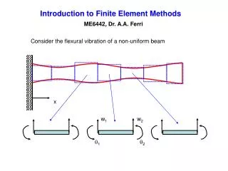
v3 u3 3 f3 v2 3 u2 f2 2 2 v1 1 u1 1 f1 Two Dimensional Examples Triangular Element Scalar-Valued, Two-Dimensional Field Problems Triangular Element Vector/Tensor-Valued, Two-Dimensional Field Problems
(Node) (Discretization with 228 Elements) (Triangular Element) (Discretization with 912 Elements) Two-Dimensional Discretization Refinement
Development of Finite Element Equation • The Finite Element Equation Must Incorporate the Appropriate Physics of the Problem • For Problems in Structural Solid Mechanics, the Appropriate Physics Comes from Either Strength of Materials or Theory of Elasticity • FEM Equations are Commonly Developed Using Direct, Variational-Virtual Work or Weighted Residual Methods Direct Method Based on physical reasoning and limited to simple cases, this method is worth studying because it enhances physical understanding of the process Variational-Virtual Work Method Based on the concept of virtual displacements, leads to relations between internal and external virtual work and to minimization of system potential energy for equilibrium Weighted Residual Method Starting with the governing differential equation, special mathematical operations develop the “weak form” that can be incorporated into a FEM equation. This method is particularly suited for problems that have no variational statement. For stress analysis problems, a Ritz-Galerkin WRM will yield a result identical to that found by variational methods.
u1 u2 F1 F2 1 2 k Simple Element Equation ExampleDirect Stiffness Derivation Stiffness Matrix Nodal Force Vector
Linear Quadratic Cubic Common Approximation SchemesOne-Dimensional Examples Polynomial Approximation Most often polynomials are used to construct approximation functions for each element. Depending on the order of approximation, different numbers of element parameters are needed to construct the appropriate function. Special Approximation For some cases (e.g. infinite elements, crack or other singular elements) the approximation function is chosen to have special properties as determined from theoretical considerations
Theoretical Basis: Formulating Element Equations • Several approaches can be used to transform the physical formulation of a problem to its finite element discrete analogue. • If the physical formulation of the problem is described as a differential equation, then the most popular solution method is the Method of Weighted Residuals. • If the physical problem can be formulated as the minimization of a functional, then the Variational Formulationis usually used.
Theoretical Basis: MWR • One family of methods used to numerically solve differential equations are called the methods of weighted residuals (MWR). • In the MWR, an approximate solution is substituted into the differential equation. Since the approximate solution does not identically satisfy the equation, a residual, or error term, results. • Consider a differential equation • Dy’’(x) + Q = 0 (1) • Suppose that y = h(x) is an approximate solution to (1). Substitution then gives Dh’’(x) + Q = R, where R is a nonzero residual. The MWR then requires that • ò Wi(x)R(x) = 0 (2) • where Wi(x) are the weighting functions. The number of weighting functions equals the number of unknown coefficients in the approximate solution.
Sources of Error in the FEM • The three main sources of error in a typical FEM solution are discretization errors, formulation errors and numerical errors. • Discretization error results from transforming the physical system (continuum) into a finite element model, and can be related to modeling the boundary shape, the boundary conditions, etc. Discretization error due to poor geometry representation. Discretization error effectively eliminated.
Sources of Error in the FEM (cont.) • Formulation error results from the use of elements that don't precisely describe the behavior of the physical problem. • Elements which are used to model physical problems for which they are not suited are sometimes referred to as ill-conditioned or mathematically unsuitable elements. • For example a particular finite element might be formulated on the assumption that displacements vary in a linear manner over the domain. Such an element will produce no formulation error when it is used to model a linearly varying physical problem (linear varying displacement field in this example), but would create a significant formulation error if it used to represent a quadratic or cubic varying displacement field.
Sources of Error in the FEM (cont.) • Numerical error occurs as a result of numerical calculation procedures, and includes truncation errors and round off errors. • Numerical error is therefore a problem mainly concerning the FEM vendors and developers. • The user can also contribute to the numerical accuracy, for example, by specifying a physical quantity, say Young’s modulus, E, to an inadequate number of decimal places.
Advantages of the Finite Element Method • Can readily handle complex geometry: • The heart and power of the FEM. • Can handle complex analysis types: • Vibration • Transients • Nonlinear • Heat transfer • Fluids • Can handle complex loading: • Node-based loading (point loads). • Element-based loading (pressure, thermal, inertial forces). • Time or frequency dependent loading. • Can handle complex restraints: • Indeterminate structures can be analyzed.
Advantages of the Finite Element Method (cont.) • Can handle bodies comprised of nonhomogeneous materials: • Every element in the model could be assigned a different set of material properties. • Can handle bodies comprised of nonisotropic materials: • Orthotropic • Anisotropic • Special material effects are handled: • Temperature dependent properties. • Plasticity • Creep • Swelling • Special geometric effects can be modeled: • Large displacements. • Large rotations. • Contact (gap) condition.
Disadvantages of the Finite Element Method • A specific numerical result is obtained for a specific problem. A general closed-form solution, which would permit one to examine system response to changes in various parameters, is not produced. • The FEM is applied to an approximation of the mathematical model of a system (the source of so-called inherited errors.) • Experience and judgment are needed in order to construct a good finite element model. • A powerful computer and reliable FEM software are essential. • Input and output data may be large and tedious to prepare and interpret.
Disadvantages of the Finite Element Method (cont.) • Numerical problems: • Computers only carry a finite number of significant digits. • Round off and error accumulation. • Can help the situation by not attaching stiff (small) elements to flexible (large) elements. • Susceptible to user-introduced modeling errors: • Poor choice of element types. • Distorted elements. • Geometry not adequately modeled. • Certain effects not automatically included: • Buckling • Large deflections and rotations. • Material nonlinearities . • Other nonlinearities.
FEM in BIOMECHANICS • The process of developing finite element models begins with the acquisition of data that will be used to define the three-dimensional geometry of the joint tissues. • These data can come from several imaging modalities, including CT and MRI. • Three-dimensional data sets are acquired and segmented, i.e., each tissue type of interest to the modeler is labeled within the data set. • From the segmented data, three-dimensional surfaces are calculated, and fully volumetric meshes (the geometric portion of the finite element model) are generated. • In the finite element analysis, the tissue types described by the finite element models are assigned specific material characteristics, and the simulation is completed, with externally calculated boundary conditions defining the specific joint behavior (e.g., flexion of the joint due to flexor tendon action). • Each of these steps is described in more detail below and will be demonstrated.
DATA ACQUISITION Accurate geometry is one key to successfully modeling joint behavior using finite element techniques. Both CT and MRI data are used in model development. Once the data are acquired, model development is independent of the imaging modality. Typically, scanners used in the medical field have a spatial resolution that is not acceptable for a precise definition of articular surfaces. A sample of high resolution CT data, in a transverse cut through a human hand.
Segmentation of the imaged, three-dimensional data sets is the process of identifying tissues and their boundaries. Edges filled in by automated segmentation and partially manually corrected. Edges generated by automated segmentation. Final mask resulting from semi-automated segmentation
SURFACE GENERATION Three-dimensional surfaces are generated directly from the masks that are the final product of the segmentation step VOLUMETRIC MESHING Mesh generation algorithms focus on volumetric tetrahedral meshes. The methods used generally rely on a subdivision algorithm of the volume. A mesh is then built by triangulating each of the cells of the volume. Slightly changing the coordinates of the vertices helps smooth the mesh and improve its quality. However, tetrahedral meshes are not suited for the dynamic simulations. Structural engineers prefer hexahedral meshes, which help speed up the convergence of the numerical algorithms.
VISUALIZATION Joint kinematics and tissue stresses calculated by the finite element code are visualized on a workstation Visualization image showing knee ligament stresses during flexion
Anatomy of Hip Joint • Largest weight bearing joint • Composed of rounded head of the femur joining the acetabulum of pelvis in a ball and socket arrangement
Damaged Femoral Head • Femoral head cartilage • The neck is cut-off as in figure • Marrow cavity is made inside the femur • Hip prosthesis is fitted either by PMMA cement or press fitted
Biomaterials • Stainless Steel Alloys • Cobalt-Chrome alloys (Vitallium) • Titanium alloys • Composites
Composite Prosthesis • Clinical studies reported early fatigue fracture of a femoral component made from laminated fiber reinforced composites. • The new designs are Constructed of short glass fibers/epoxy resin and CF/PEEK composites.
Composite Model Basic Composite Model With Elements
Conical Stem • Cemented prosthesis model contains three main parts: • Conical Stem with head • Cement layer • Cortical bone Basic Model
Chopped Fiber Core Model With Chopped Fiber Core
Parts Material Young’s Modulus (MPa) Poisson's Ratio Geometrical Parameter (All dimensions are in mm) Head and Stem Ti6Al4V 110x103 0.33 Sphere radius 25 Stem radius 10 Stem outer radius 10 Stem inner radius 7.5 Cement Layer UHMWPE-AL2O3 1x10³ 0.39 Inner radius 10.5 Outer radius 12.2182 Length 100 Cortical Bone AS4/PEEK 3x10³ 0.30 Inner radius 20.5 Outer radius 30 Material Properties Material Properties Used for Analysis of Total Hip Prosthesis
Maximum Shear Stress Region Enlarged View of the Deformed Stem and Cortical Bone Showing the Maximum Shear Stress Region (Path Aa)
Stem Inner Radius (in mm) Stem Length (in mm) Neck Length (in mm) Neck Inclination (in degree) Maximum Shear Stress (in MPa) Maximum Shear Stress (in MPa) Maximum Shear Stress (in MPa) Maximum Shear Stress (in MPa) 45 7.5 45 145 17.314 17.314 13.337 17.314 145.5 47.5 15.522 17.376 47.5 8 20.383 20.655 50 147.5 21.033 17.314 8.5 50 22.964 19.443 52.5 150 25.363 20.919 152.5 17.144 155 20.262 Variation of Shear Stresses Variation of Maximum Shear Stress With System Parameters
Continued... • The variation in the above parameters do not show a particular trend • Hence the design optimization has been carried out to minimize the magnitude of maximum shear stress
Parts State Variables Design Variables Femur Sphere Radius 25 mm Stem Outer Radius 10 mm Stem Inner Radius 7.5 mm Neck Inclination 450 Stem Length 145.5 mm Neck length 50 mm Hip Prosthesis Dimensions of Hip Prosthesis Before Optimization
Design Variables Dimension (mm) Stem outer radius 9.9301 Stem inner radius 8.0405 Stem length 153.22 Neck length 50.975 Femoral Components Design Variables of Femoral Components After Optimisation
Shear Stresses SXY x-ycomponent SYZ y-z component SXZ z-x component Shear Stresses in the Interface of Stem and Cortical Bone