PRESTENSIONING & POST- TENSIONING
PRESTENSIONING & POST- TENSIONING. METHODS OF PRESTRESSING IN CONCRETE. PRESTRESSED CONCRETE. PRINCIPLE – Using high tensile strength steel alloys producing permanent pre-compression in areas subjected to Tension.

PRESTENSIONING & POST- TENSIONING
E N D
Presentation Transcript
PRESTENSIONING & POST- TENSIONING METHODS OF PRESTRESSING IN CONCRETE
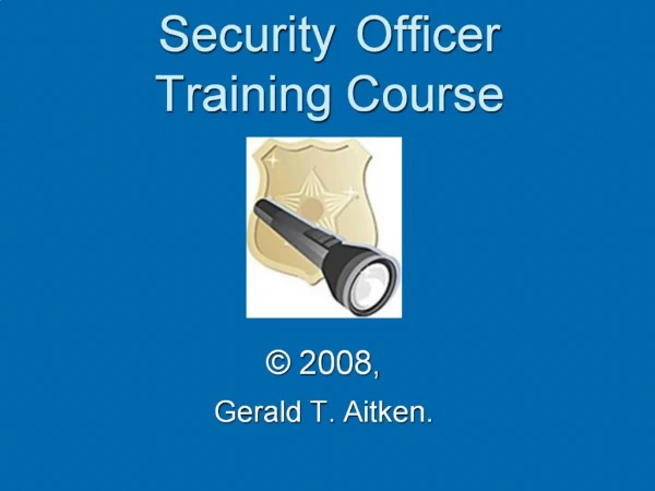
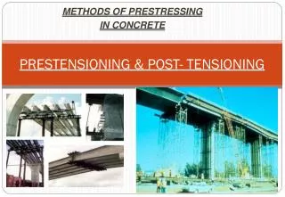
PRESTRESSED CONCRETE • PRINCIPLE – Using high tensile strength steel alloys producing permanent pre-compression in areas subjected to Tension. • A portion of tensile stress is counteracted thereby reducing the cross-sectional area of the steel reinforcement . • METHODS :- a) Pretensioning b)Post-tensioning • PRETENSIONING :- Placing of concrete around reinforcing tendons that have been stressed to the desired degree. • POST-TENSIONING :- Reinforcing tendons are stretched by jacks whilst keeping them in serted in voids left pre-hand during curing of concrete. • These spaces are then pumped full of grout to bond steel tightly to the concrete. STEEL BARS BEING STRETCHED BY JACKS
POST - TENSIONING • WHAT IS POST-TENSIONING? • Post-tensioning- is a method of reinforcing (strengthening) concrete or other materials with high-strength steel strands called tendons. • Post-tensioning allows construction that would otherwise be impossible due to either site constraints or architectural requirements. • Requires specialized knowledge and expertise to fabricate, assemble and install. • After adequate curing of concrete, reinforcing tendons (placed in side the voids of the structure) are tensioned/stretched by jacks on the sides & grouts filled with appropriate mix. • Applications – a) Structural members beams, bridge-deck panels, Roof –Slabs, Concrete Silos Etc.
BENEFITS • Concrete is very strong in compression but weak in tension,\ • This deflection will cause the bottom of the beam to elongate slightly & cause cracking. • Steel reinforcing bars (“rebar”) are typically embedded in the concrete as tensile reinforcement to limit the crack widths. • Rebar is what is called “passive” reinforcement however; it does not carry any force until the concrete has already deflected enough to crack. • Post-tensioning tendons, on the other hand, are considered “active” reinforcing. • Because it is prestressed, the steel is effective as reinforcement even though the concrete may not be cracked . • Post-tensioned structures can be designed to have minimal deflection and cracking, even under full load. Post –Tensioned Structure
ADVANTAGES/APPLICATIONS This innovative form is result of post tensioning. • Post-tensioning allows longer clear spans, thinner slabs, fewer beams and more slender, dramatic elements. • Thinner slabs mean less concrete is required. It means a lower overall building height for the same floor-to-floor height. • Post-tensioning can thus allow a significant reduction in building weight versus a conventional concrete building with the same number of floors reducing the foundation load and can be a major advantage in seismic areas. • A lower building height can also translate to considerable savings in mechanical systems and façade costs. • Another advantage of post-tensioning is that beams and slabs can be continuous, i.e. a single beam can run continuously from one end of the building to the other. • Reduces occurrence of cracks . • Freezing & thawing durability is higher than non prestressed concrete. Bridge decks
Post-tensioning is the system of choice for parking structures since it allows a high degree of flexibility in the column layout, span lengths and ramp configurations. • In areas where there are expansive clays or soils with low bearing capacity, post-tensioned slabs-on-ground and mat foundations reduce problems with cracking and differential settlement. • Post-tensioning allows bridges to be built to very demanding geometry requirements, including complex curves, and significant grade changes. • Post-tensioning also allows extremely long span bridges to be constructed without the use of temporary intermediate supports. This minimizes the impact on the environment and avoids disruption to water or road traffic below. • In stadiums, post-tensioning allows long clear spans and very creative architecture. \ • Post-tensioning can also be used to produce virtually crack-free concrete for water-tanks. • The high tensile strength & precision of placement gives maximum efficiency in size & weight of structural members. • Applications of various prestressed techniques enable quick assembly of standard units such as bridge members,building frames, bridge decks providing cost-time savings.
CONSTRUCTION • In slab-on-ground construction, unbonded tendons are typically prefabricated at a plant and delivered to the construction site, ready to install. • The tendons are laid out in the forms in accordance with installation drawings that . • After the concrete is placed and has reached its required strength, usually between 3000 and 3500 psi (“pounds per square inch”), the tendons are stressed and anchored. • The tendons, like rubber bands, want to return to their original length but are prevented from doing so by the anchorages. • The fact the tendons are kept in a permanently stressed (elongated) state causes a compressive force to act on the concrete. • The compression that results from the post-tensioning counteracts the tensile forces created by subsequent applied loading (cars, people, the weight of the beam itself when the shoring is removed). • This significantly increases the load-carrying capacity of the concrete. • Since post-tensioned concrete is cast in place at the job site, there is almost no limit to the shapes that can be formed. Limitations of Prestressing The limitations of prestressed concrete are few and really depend only upon the imagination of the designer and the terms of his brief. The only real limitation where prestressing is a possible solution may be the cost of providing moulds for runs of limited quantity of small numbers of non-standard units.
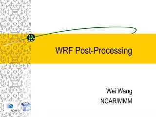
Method of post-tensioning Wedges tensioned by jacks Tendons TENDONS
PRESTRESSED CONCRETE • Prestressed concrete, invented by Eugene Frevssinet in 1928 is a method for overcoming concrete’’s natural weakness in tension . It can be used to produce beams , floors or bridges with a longer span than is practical with ordinary reinforced concrete. • It can be accomplished in three ways: pre-tensioned concrete, and bonded or unbonded. Pre-tensioned concrete • Pre-tensioned concrete is cast around already tensioned tendons. • This method produces a good bond between the tendon and concrete, which both protects the tendon from corrosion and allows for direct transfer of tension. • The cured concrete adheres and bonds to the bars and when the tension is released it is transferred to the concrete as compression by static friction. • However, it requires stout anchoring points between which the tendon is to be stretched and the tendons are usually in a straight line. • Thus, most pretensioned concrete elements are prefabricated in a factory and must be transported to the construction site, which limits their size. • Pre-tensioned elements may be balcony elements, lintels , floor slabs, beams or foundation piles.
Bonded post-tensioned concrete • Bonded post-tensioned concrete is the descriptive term for a method of applying compression after pouring concrete and the curing process (in situ). • The concrete is cast around a plastic, steel or aluminium curved duct, to follow the area where otherwise tension would occur in the concrete element. • A set of tendons are fished through the duct and the concrete is poured. Once the concrete has hardened, the tendons are tensioned by hydraulic jacks. • When the tendons have stretched sufficiently, according to the design specifications they are wedged in position and maintain tension after the jacks are removed, transferring pressure to the concrete. • The duct is then grouted to protect the tendons from corrosion. This method is commonly used to create monolithic slabs for house construction in locations where expansive soils create problems for the typical perimeter foundation. • All stresses from seasonal expansion and contraction of the underlying soil are taken into the entire tensioned slab, which supports the building without significant flexure. Post-stressing is also used in the construction of various bridges. • The advantages of this system over unbonded post-tensioning are: DECK STEEL LAYING
Large reduction in traditional reinforcement requirements as tendons cannot destress in accidents. • Tendons can be easily 'weaved' allowing a more efficient design approach. • Higher ultimate strength due to bond generated between the strand and concrete. • No long term issues with maintaining the integrity of the anchor/dead end. Unbonded post-tensioned concrete • Unbonded post-tensioned concrete differs from bonded post-tensioning by providing each individual cable permanent freedom of movement relative to the concrete. • To achieve this, each individual tendon is coated with a grease (generally lithium based) and covered by a plastic sheathing formed in an extrusion process. • The transfer of tension to the concrete is achieved by the steel cable acting against steel anchors in the perimeter of the slab. • The main disadvantage over bonded post-tensioning is the fact that a cable can destress itself and burst out of the slab if damaged (such as during repair on the slab). The advantages of this system over bonded post-tensioning are:
External Prestressing • This refers to the case where prestressing tendons are placed outside the concrete section and the prestressing force is transferred to a structural member through end anchorages or deviators. Advantages of external prestressing include the possibility of monitoring and replacing tendons, ease in concreting and hence better concrete quality and the use of narrower webs. External prestressing is being increasingly used in the construction of new bridges and is a primary method for the strengthening and rehabilitation of existing structures. • At NUS, a three-year project on the application of external prestressing in structural strengthening has been completed, and this has resulted in design charts being developed for such applications. Works were also carried out on the use of fibre-reinforced polymer (FRP) reinforcement as external tendons in both simply supported and continuous beams.
APPLICATIONS The lower and upper terraces cantilever over the stream below. The temporary structural steel shoring was placed beneath the main level terrace. • Fallingwater is comprised of a series of concrete cantilever “trays” 30-ft. above a waterfall. Previous efforts failed to permanently address excessive deflections of the cantilever and repair the cracks. After a thorough design review, the owner and engineer selected an external post-tensioning solution for its durability, aesthetics and structural unobtrusiveness. • Construction plans called for strengthening of three support girders spanning in the north-south direction with multistrand post-tensioning tendons consisting of multiple 0.5” diameter strands. • Thirteen strand tendons were placed on each side of two girders. One 10-strand tendon was placed on the western side of the third girder (access on the eastern side of this girder was not available). Eight monostrand tendons, 0.6” diameter, were slated for the east-west direction. • The monostrand tendons were stressed in the east-west direction and then the multistrand tendons were stressed in the north-south direction and grouted with a high quality, low-bleed cementitious grout mixture. • VSL’s scope of work also included welding steel cover plates, attaching structural steel channels, injecting epoxy grout, doweling reinforced cast in place concrete blocks and the installation of near surface mounted carbon fiber rods. Challenged with maintaining Fallingwater’s original setting, furnishings and artwork, the project was successfully completed in six months. Frank Lloyd Wright's Fallingwater Mill Run, Pennsylvania
Cline Avenue Bridge Gary, Indiana • The Cline Avenue Bridge (SR 912) is a predominately cast-in-place post-tensioned structure located in Gary, Indiana. The bridge mainline is over 6,000 LF, has two adjacent segments nearly 35 feet wide each, and contains four connecting ramps. An inspection and analysis team was assembled to perform a thorough investigation of the bridge. The team concentrated on the existing post-tensioning system and interior and exterior concrete cracks. The engineer retained VSL to assist with the inspection of the tendons. • VSL approached the Cline Avenue project with a guideline that outlines a statistically sound method of sampling the tendons. A statistical sample pool (which consisted of the mainline structure and the ramps) was defined by referencing the American National Standard Institute’s (ANSI) guideline “Sampling Procedures and Tables for Inspection by Attributes as published by the American Society for Quality Control (1993).” • The probable void locations throughout the structure’s mainline segments and ramps were initially identified by VSL to appropriately distribute the sampling population. Such areas consisted of high points, areas approaching and leaving the high points, and couplers. • Using non-destructive Ground Penetrating Radar (GPR) and field layout drawings, VSL located existing post-tensioning tendons. Once the layout was performed, specific tendons throughout the bridge and ramp structures were sampled by drilling into the duct and exposing the tendon for visual inspection. The use of a borescope allowed for detailed visual inspection of the tendon and also captured video footage to share with the owner and the engineer. After review of each inspection, VSL placed epoxy in the borescope hole to protect the tendons from air and moisture intrusion. When voids were encountered, the project team observed and documented the condition of the strand based on the PCI Journal guideline, “Evaluation of Degree of Rusting on Prestressed Concrete Strand.” VSL used vacuum grouting technology to fill the void, thereby protecting the previously exposed strand. • The tendon inspection data was analyzed with other findings (such as crack survey findings) to determine what type of rehabilitation was required. VSL’s goal to establish a statistically sound sample of physically inspected tendons that provided valid data as to the current state of the existing PT system was accomplished
85th Street Bridge Valley Center, Kansas • The 85th Street North Bridge is a seven span post-tensioned haunched slab bridge with a typical span of 26 meters for the middle five spans, and 20 meters at the ends. This 170 meter long bridge accommodates two lanes of traffic reaching over the Wichita Valley Center Floodway. VSL post-tensioning systems utilized for this project include 5-19 longitudinal tendons as well as 6-4 transverse tendons. • Post-tensioned haunched slab bridges are noted for ease of construction. Once the geometry of the bridge falsework has been obtained, prefabricated spacer frames are set into place. The spacer frames serve as templates for profiling the longitudinal post-tensioning tendons and aid in the placement of the remaining conventional reinforcement. Transverse tendons maintain mid-depth placement along the geometry of the haunched slab and provide the minimum pre-compression over the length of the structure. • The finished product has several advantages over conventionally reinforced concrete. Dead loads are balanced by the use of longitudinal post-tensioning reducing the sustained loading and associated creep. Corrosion resistance is increased due to the encapsulation of the post-tensioning reinforcement. Through the use of transverse post-tensioning, added compression improves the longevity of the structure by adding resistance to de-icing methods such as salt and magnesium chloride. Post-tensioned haunched slab bridges allow for a larger span to depth ratio than that of conventionally reinforced haunched slab bridges. The labor and material savings on mild reinforcement is another clear advantage to using post-tensioning for this application. Overlooking the 85th Street Bridge prior to concrete placement
Colorado Convention Center Expansion Denver, Colorado • The Colorado Convention Center Expansion project is a 1.4 million square foot expansion of the existing facility. This was a multi-level project, which included a 1,000-car attached parking garage. • The garage above the street was constructed using precast tees and columns with a cast-in-place topping slab. In order to maintain regular spacing for the columns in the precast section of the garage and still maintain an unobstructed path for the road and light rail, large post-tensioned transfer girders were required to support several of the columns above. The transfer girders allowed for the placement of columns required for the precast design despite the restricted column locations at the street level. • Post-tensioning the transfer girders resulted in smaller dimensions than a conventional reinforced concrete design, an important factor given the girders are over 7 feet high and up to 7 feet wide and a larger section would not fit within the space constraints of the building. The girders could not be stressed until after the precast garage was fully erected and the topping slab poured on the truck dock. Temporary columns were placed under the girders to support the load until stressing. • The effective post-tensioning force required for the beams ranged from 2176 to 5457 kips. A multistrand bonded system was installed
The Seward Silo project involved the post-tensioning of three interconnected ash silos that are part of the Seward Re-Powering Project in Seward, Pennsylvania. The overall project involved the construction of a new, state-of-the-art 208 MW power plant designed to burn low-grade coal that can not be burned in ordinary coal plants. This is a design-build project with Drake-Fluor Daniel as the owner/construction manager until the completed plant is turned over to Reliant Energy, the ultimate owner. • T.E. Ibberson Company was contracted to build three 187’-6” tall, interconnected, in-line silos; two 82’-4” diameter fly ash silos and one 64’-8” diameter bed ash silo. The silos were built using the slip-form method of construction and are believed to be the first interconnected silos in the world built using post-tensioning as the primary circumferential reinforcement. • VSL’s work was performed from November 2003 through February 2004, during the second coldest winter on record locally. Significant snowfall and subzero temperatures made progress challenging, yet with a strong focus on safety, both cold-related and otherwise, the job was completed with no incidents. The job required close coordination between the various trades working in close proximity and constant communication between parties working above and below VSL’s work locations to phase the work to avoid having personnel under an active work zone. • The strand installation, stressing and grouting operations were completed successfully, with cold-weather grouting made possible through a variety of heating methods. Seward Silo
THE BICYCLE WHEEL • Bicycle wheel as we know it today - each is associated with an application of prestressing to a structural system. • The first and most obvious is the tensioned spokes - the rider's weight is carried from the forks to the ground not by hanging off the top spokes, but by reducing the pretension in the lower spokes - only a couple of spokes are carrying the load at any one time. • The second is the pneumatic tyre, where the compressive load is carried to the ground by reducing the tension in the sidewall. The air pressure in the tyre does not change when the load is applied. • The final prestressing system is the tyre cord, which is shorter than the perimeter of the rim. The cord is thus in tension, holding the tyre on the rim, which enables the pretension in the sidewalls to be reacted
EQUIPMENTS :- • T6Z-08 Air Powered Grout Pump • Pumps cement grout only, no sand. 32 Gallon Mixing Tank. Mixes up to 2 sacks of material at once and allows for grout to be pumped during mixing or mixed without pumping.
Colloidal Grout Plant • The heavy duty, high volume Colloidal Grout Plant is favored for precision post-tension grouting. The unit features a high speed shear mixer that thoroughly wets each particle and discharges the mixed material into a 13 cubic foot capacity agitating holding tank. A direct coupled progressing cavity pump delivers slurries at a rate of up to 20 gpm and pressures of up to 261 psi. The unit easily mixes and pumps slurries of Portland cement, fly ash, bentonite, and lime flour. All controls are conveniently located on the operator platform for easy one-man control.
T7Z Hydraulic Jacks • Used for testing and pre-stressing anchor bolts. Available with up to 5-1/8" center hole. Unit comes with ram, pump, gauge, hoses, jack stand, high strength coupling, high strength test rod, plate, hex nut and knocker wrench. Calibrations are available upon request. • Note: Jack pull rods should have a higher capacity than the anchor rod.
T80 Post-Tensioning Jacks • With the T80 series the enclosed bearing housing contains a geared socket drive to tighten the bolt hex nut during tensioning. Test jack housing will accommodate up to a 9” deep pocket. T80 Post-Tensioning Jacks
T8Z-18 Hydraulic Torque Wrench • The hydraulic torque wrench is used for tensioning anchors in tight fitting locations where it would be difficult to use an hydraulic jack. The wrench is also recommended for use when setting the large diameter Spin-Lock anchors. The torque wrenches are light weight and can achieve a maximum of 8,000 ft-lbs. Torque Tensioning charts Williams products can be found here.
T8Z Torque Wrench • For applying torque to the anchor bolt when setting the anchor. Torque Tensioning charts Williams products can be found here. T8Z-04 Torque Multiplier (4:1) For use with T8Z Torque Wrench. Other sizes available
T1Z & T2Z Long Fitting Tool Adapters • For driving hex nuts and setting tools, typically with our Spin-Lock anchor systems. Works with torque wrench or impact gun.Available with 1" or 1-1/2" square drive. Please specify square drive for compatability with your equipment. T1Z Deep Socket 2Z Regular Socket K3F-26 Long Fitting Wrench Adapter For applying torque to recessed anchor nuts that are under tension when using hydraulic jacks. Available in all anchor sizes.
Corrosion Protection Methods of Corrosion Protection
Methods of Corrosion Protection • Epoxy Coating Fusion bonded epoxy coating of steel bars to help prevent corrosion has been successfully employed in many applications because of the chemical stability of epoxy resins. Epoxy coated bars and fasteners should be done in accordance with ASTM A-775 or ASTM 934. Coating thickness is generally specified between 7 to 12 mils. Epoxy coated bars and components are subject to damage if dragged on the ground or mishandled. Heavy plates and nuts are often galvanized even though the bar may be epoxy coated since they are difficult to protect against abrasion in the field. Epoxy coating patch kits are often used in the field for repairing nicked or scratched epoxy surfaces. Pre-Grouted Bars Cement Grout filled corrugated polyethylene tubing is often used to provide an additional barrier against corrosion attack in highly aggressive soils. These anchors are often referred to as MCP or Multiple Corrosion Protection anchors. The steel bars are wrapped with an internal centralizer then placed inside of the polyethylene tube where they are then factory pre-grouted. When specifying couplings with MCP ground anchors, verify coupling locations with a Williams representative.
Hot Dip Galvanizing • Zinc serves as a sacrificial metal corroding preferentially to the steel. Galvanized bars have excellent bond characteristics to grout or concrete and do not require as much care in handling as epoxy coated bars. However, galvanization of anchor rods is more expensive than epoxy coating and often has greater lead time. Hot dip galvanizing bars and fasteners should be done in accordance with ASTM A-153. Typical galvanized coating thickness for steel bars and components is between 3 and 4 mils. 150 KSI high strength steel bars should always be mechanically cleaned (never acid washed) to avoid problems associated with hydrogen embrittlement. Extruded Polyethylene Williams strand tendons contain an extruded high density polyethylene sheathing around each individual strand in the free-stressing portion of the anchorage. The sheathing is minimum 60 mils thick and applied once the 7-wire strand has been coated with a corrosion inhibiting compound. Extruded polyethylene sheathing provides a moisture tight barrier for corrosion protection and allows the strand to elongate freely throughout the free-stressing length during the prestressing operation
Corrosion Inhibiting Wax or Grease with Sheath Williams corrosion inhibiting compounds can be placed in the free stressing sleeves, in the end caps, or in the trumpet areas. Often bars are greased/waxed and PVC is slipped over the greased/waxed bar prior to shipping. Each are of an organic compound with either a grease or wax base. They provide the appropriate polar moisture displacement and have corrosion inhibiting additives with self-healing properties. They can be pumped or applied manually. Corrosion inhibiting compounds stay permanently viscous, chemically stable and non-reactive with the prestressing steel, duct materials or grout. Both compounds meet PTI standards for Corrosion Inhibiting Coating.
Heat Shrink Tubing • Heat Shrink Tubing provides a corrosion protected seal when connecting smooth or corrugated segments. Epoxy Coating Patch Kits Epoxy Coating Patch Kits are available upon request. Screw-OnPVC Cap Fiber Reinforced Nylon Cap StrandEnd Cap Steel Tube Welded on Flange with Threaded Screw Connections
Field Splice for Bars • Continuous corrosion protection can even be accomplished for the MCP Pregrouted anchors manufactured from Williams Form Engineering. To achieve the equivalent levels of corrosion protection the coupled sections of bar anchors can be wrapped in a grease impregnated tape that is further protected with heat shrink sleeving. This scheme is acceptable by most governing agencies and is specified in the PTI Recommendations for Prestresed Rock and Soil Anchors.