MD 121 Machine Construction
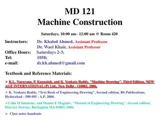
MD 121 Machine Construction. Saturdays, 10:00 am– 12:00 am @ Room 420. Instructors: Dr. Khaled Ahmed, Assistant Professor Dr. Wael Khair, Assistant Professor Office Hours: Saturdays 2-3; Tel: 1058; e-mail: dr.kh.ahmed@gmail.com. Textbook and Reference Materials:

MD 121 Machine Construction
E N D
Presentation Transcript
MD 121 Machine Construction Saturdays, 10:00 am– 12:00 am @ Room 420 Instructors: Dr. Khaled Ahmed, Assistant Professor Dr. Wael Khair, Assistant Professor Office Hours:Saturdays 2-3; Tel:1058; e-mail:dr.kh.ahmed@gmail.com • Textbook and Reference Materials: • K.L. Narayana, P. Kannaiah, and K. Venkata Reddy, "Machine Drawing", Third Edition, NEW AGE INTERNATIONAL (P) Ltd., New Delhi - 110002, 2006. • K. Venkata Reddy, “Text Book of Engineering Drawing", Second edition, BS Publications, Hyderabad - 500 095 - A.P, 2008. • Colin H Simmons, and Dennis E Maguire, "Manual of Engineering Drawing", Second edition, Elsevier Newnes, Burlington MA 01803, 2004. • Class notes handouts
Intended Learning Outcomes (ILO’s) • Knowledge and Understanding: • You will learn how to; • Understand the basic methods for machine assembly • Distinguish between the data and instructions used for both working and assembly drawings • Professionally deduce and sketches both working and assembly drawings according to the international standards • Intellectual • You will learn how to; • Motivate your intellectual abilities to imagine and deduce machine parts and a whole machine from the drawings views. • Motivate your imagination for producing new ideas and methods in machine drawings. • Create new concepts for the design of machine components and also for assembly of them. • Professional Skills • You will learn how to; • Practice the standard drawing methods to generate both working and assembly mechanical drawings. • Write and specify correctly and according to standards the instructions and machining marks and the dimensions on mechanical drawings. • General • You will learn how to; • Cooperate to work in groups through small scale projects • Work coherently and successfully as a part of a team.
Course Outline • Problems Sheets will be handed in the class after discussed in the lecture • An extra class will be given to students with Mark “C” every next Saturday • A term project will be given by Dr. Wael and will be submitted at the end of the term
Course Assessment and Evaluation We shouldn’t learn to get marks We shouldn’t learn to get certificates We shouldn’t learn to get titles • Why do we learn? • To gain knowledge • To achieve objectives • To build career • Why do we need assessment and evaluation? • To measure the achieved objectives • To point out what in need for improvements Class Work ……………………………………………………..10% Extra Class Work (Mark “C” students will get bonus) ……..10% Course Project ………………….……………………………… 10% Lecture Quizzes ……………..………………………………… 5% Mid Term (November 27th 2010)…………………………… 10% Final Exam (Sit in Exam)………………………………………65%
How to Keep Your Drawing Clean Do Don’t
Drawing Sheet Size Assembly Drawing Working Drawing
PROJECTION SYSTEMS 1. First angle system - European country- ISO standard First Quadrant 2. Third angle system - Canada, USA, Japan, Thailand Third Quadrant
ORTHOGRAPHIC PROJECTION 3rd angle system 1stangle system
ORTHOGRAPHIC VIEWS 3rd angle system 1stangle system Folding line Folding line Folding line Folding line
ORTHOGRAPHIC VIEWS 3rd angle system 1stangle system Top View Right Side View Front View Front View Right Side View Top View
PROJECTION SYMBOLS First angle system Third angle system
3. Which is in correct first angle projection ? (180 sec) b) a) c) d) 0 45 90 135 180
4. Which is in correct third angle projection ? (180 sec) b) a) c) d) 0 45 90 135 180
5. Which is a wrong 3rd angle orthographic views ?(180 sec) b) a) c) d) 0 45 90 135 180
VIEW SELECTION STEPS 1. Orient the object to the best positionrelative to a glass box. 2. Select the front view. 3. Select adjacent views.
The object should be placed in its natural position. The object should presents its features in actualsize and shape in orthographic views. STEP 1 : Orient the Object GOOD NO !
The object’s longest dimension should be presented as a width. STEP 2 : Select a Front View First choice Second choice Waste more space Inappropriate GOOD
The adjacent views that are projected from the selected front view should appear in its natural position. STEP 2 : Select a Front View Inappropriate
Choose the view that have the fewest number ofhidden lines. STEP 2 : Select a Front View GOOD Inappropriate
Choose the view that have the fewest number ofhidden lines. STEP 3 : Select an Adjacent View GOOD Inappropriate GOOD Inappropriate
Choose the minimum number of views that can represent the major features of the object. STEP 3 : Select an Adjacent View Necessary Hole’s location can be specified on the same view. Easy to understand Difficult to interprete. Necessary
Choose the views that are suitable to a drawingspace. STEP 3 : Select an Adjacent View POOR Not enough space for dimensioning.
Choose the views that are suitable to a drawingspace. STEP 3 : Select an Adjacent View GOOD
D W H D W H Example: View selection mislead to… F.V. Three views F.V. & T.V. F.V. & R.S.V. Size description Shape description
Flat part having a uniform thickness. ONE-VIEW DRAWING 1 Thick These 2 views provide only informationabout the part thickness ! Unnecessary
Cylindrical-shaped part. ONE-VIEW DRAWING Unnecessary Repeat ! Infer from CL Unnecessary
There exists an identical view. TWO-VIEW DRAWING Repeat ! Unnecessary
The 3rd view has no significant contours of the object. TWO-VIEW DRAWING Unnecessary
The 3rd view has no significant contours of the object. TWO-VIEW DRAWING Unnecessary
1. Which should be the natural position of the light bulb ? (20 sec) a b) c) d) 0 5 10 15 20
E D B A C F 2. Which are the necessary views ? (60 sec) • A-C-E • E-B-D • E-A • E-C 0 15 30 45 60
A(FV) B(FV) C(FV) D(FV) A(TV) B(SV) C(SV) D(SV) Projection
Drawing Reading Rear tool post is generally used on capstan lathes, mainly for parting-off operations. It is fixed on the cross-slide in the slots, provided at the rear side of the lathe