Assembly Sequence Plan
Assembly Sequence Plan. T. Brown. Princeton Plasma Physics Laboratory Oak Ridge National Laboratory. NCSX Lehman Review Princeton Plasma Physics Laboratory Princeton, NJ August 15-17, 2007. Assembly Sequence Plan. Summarize the overall machine assembly steps

Assembly Sequence Plan
E N D
Presentation Transcript
Assembly Sequence Plan T. Brown Princeton Plasma Physics Laboratory Oak Ridge National Laboratory NCSX Lehman Review Princeton Plasma Physics Laboratory Princeton, NJ August 15-17, 2007
Assembly Sequence Plan • Summarize the overall machine assembly steps • Provide a background of the key assembly elements. - Basis for assembly cost estimates. • Briefly review and status the assembly sequence plan
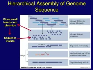
NCSX device assembly The NCSX device is assembled in five stages: • Stage 1 – vacuum vessel period preparation • Stage 2 – Modular Coil Half Period assembly • Stage 3 – MCHP assembled over a VV period • Stage 4 – no longer used (old TF half period assembly) • Stage 5 – final field period assembly • Stage 6 – final machine assembly Each stage now corresponds to an assembly Station where installation sequences will take place.
The MCHP is assembled at Station 2 The completed assembled tolerance for the MCHP is ± 0.010”. Type A Type C Type-B
Vacuum Vessel Period Module Coil Half Period Module Coil Half Period MCHP installed over the VV occurs at Station 3 The design intent for Station 3 is pass two MCHP assemblies over the VV (without hitting it) and accurately position mating flange. The tolerance for the assembled period is ± 0.020”.
The MCHP must follow a prescribed path The assembly path is mounted on screens in Station 3 to guide the motion of a MCHP over the VV period The assembly approach being used has been successfully demonstrated A 1” stand-off to vessel surface components
1.528” MCHP assembly clearances Within the MCHP assembly path minimum clearances between the MC and VV shell components are encountered. .45” clearance in wing region
The field period is completed inStation 5 FPA on support stand VV ports installed TF temporarily positioned Completed period assembly TF final fit-up
The NCSX device is completed in Station 6 Permanent machine supports Temporary FPA supports
Type-C modular coil interface Type-C flange interfaces Each of the three field periods are assembled concurrently to join Type-C flanges
VV spool pieces interface As the Type-C flanges come together VV flanges will begin to mate with the adjoining spool pieces.
Station 6 incorporates Station 2 positioning techniques TF coils at the Period ends Each FPA will be properly oriented in their final position using the same technique that has been developed in assembling the MCHP’s and then pulled back to a pre-fit position.
Assembly Sequence Plan Rev 7 of the assembly sequence plan issued June 6th provides the bases for the FPA and machine assembly cost estimates and schedules.Detailed assembly steps for Stations 2, 3, 5 and 6 are detailed in ~ 28 pages of an Excel spreadsheet document.
Summary The Rev 7 release of the assembly plan provides the basis for FPA and machine assembly providing far greater detail than was available at the December Lehman review.