Download
1 / 29
300 likes | 547 Vues
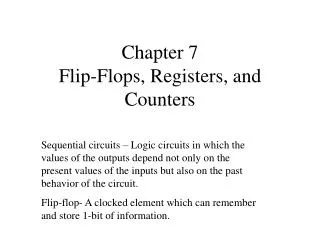
Chapter 7 Henry Hexmoor Registers and RTL. 1. 10. 00. 1. 1. 01. 11. 1. Counters. Counters are a specific type of sequential circuit. Like registers, the state, or the flip-flop values themselves, serves as the “output.” The output value increases by one on each clock cycle.

E N D
Chapter 7Henry HexmoorRegisters and RTL Henry Hexmoor
1 10 00 1 1 01 11 1 Counters • Counters are a specific type of sequential circuit. • Like registers, the state, or the flip-flop values themselves, serves as the “output.” • The output value increases by one on each clock cycle. • After the largest value, the output “wraps around” back to 0. • Using two bits, we’d get something like this: 2
Benefits of counters • Counters can act as simple clocks to keep track of “time.” • You may need to record how many times something has happened. • How many bits have been sent or received? • How many steps have been performed in some computation? • All processors contain a program counter, or PC. • Programs consist of a list of instructions that are to be executed one after another (for the most part). • The PC keeps track of the instruction currently being executed. • The PC increments once on each clock cycle, and the next program instruction is then executed. 3
10 00 01 11 A slightly fancier counter • Let’s try to design a slightly different two-bit counter: • Again, the counter outputs will be 00, 01, 10 and 11. • Now, there is a single input, X. When X=0, the counter value should increment on each clock cycle. But when X=1, the value should decrement on successive cycles. • We’ll need two flip-flops again. Here are the four possible states: 4
10 00 01 11 0 0 1 0 1 1 1 0 The complete state diagram and table • Here’s the complete state diagram and state table for this circuit. 5
D flip-flop inputs • If we use D flip-flops, then the D inputs will just be the same as the desired next states. • Equations for the D flip-flop inputs are shown at the right. • Why does D0 = Q0’ make sense? D1 = Q1 Q0 X D0 = Q0’ 6
The counter in LogicWorks • Here are some D Flip Flop devices from LogicWorks. • They have both normal and complemented outputs, so we can access Q0’ directly without using an inverter. (Q1’ is not needed in this example.) • This circuit counts normally when Reset = 1. But when Reset is 0, the flip-flop outputs are cleared to 00 immediately. • There is no three-input XOR gate in LogicWorks so we’ve used a four-input version instead, with one of the inputs connected to 0. 7
JK flip-flop inputs • If we use JK flip-flops instead, then we have to compute the JK inputs for each flip-flop. • Look at the present and desired next state, and use the excitation table on the right. 8
JK flip-flop input equations • We can then find equations for all four flip-flop inputs, in terms of the present state and inputs. Here, it turns out J1 = K1 and J0 = K0. J1 = K1 = Q0’ X + Q0 X’ J0 = K0 = 1 9
The counter in LogicWorks again • Here is the counter again, but using JK Flip Flop n.i. RS devices instead. • The direct inputs R and S are non-inverted, or active-high. • So this version of the circuit counts normally when Reset= 0, but initializes to 00 when Reset is 1. 10
Asynchronous Counters • This counter is called asynchronous because not all flip flops are hooked to the same clock. • Look at the waveform of the output, Q, in the timing diagram. It resembles a clock as well. If the period of the clock is T, then what is the period of Q, the output of the flip flop? It's 2T! • We have a way to create a clock that runs twice as slow. We feed the clock into a T flip flop, where T is hardwired to 1. The output will be a clock who's period is twice as long. 11
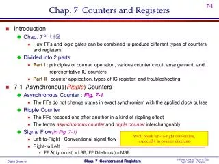
Asynchronous counters If the clock has period T. Q0 has period 2T. Q1 period is 4T With n flip flops the period is 2n. 12
3 bit asynchronous “ripple” counter using T flip flops • This is called as a ripple counter due to the way the FFs respond one after another in a kind of rippling effect. 13
Synchronous Counters • To eliminate the "ripple" effects, use a common clock for each flip-flop and a combinational circuit to generate the next state. • For an up-counter,use an incrementer => Incre-menter S3 D3 Q3 A3 Q2 S2 D2 A2 S1 Q1 D1 A1 S0 D0 Q0 A0 Clock 14
Incrementer Synchronous Counters (continued) • Internal details => • Internal Logic • XOR complements each bit • AND chain causes complementof a bit if all bits toward LSBfrom it equal 1 • Count Enable • Forces all outputs of ANDchain to 0 to “hold” the state • Carry Out • Added as part of incrementer • Connect to Count Enable ofadditional 4-bit counters toform larger counters 15
Current State Next State Q8 Q4 Q2 Q1 Q8 Q4 Q2 Q1 0 0 0 0 0 0 0 1 0 0 0 1 0 0 1 0 0 0 1 0 0 0 1 1 0 0 1 1 0 1 0 0 0 1 0 0 0 1 0 1 0 1 0 1 0 1 1 0 0 1 1 0 0 1 1 1 0 1 1 1 1 0 0 0 1 0 0 0 1 0 0 1 1 0 0 1 0 0 0 0 Design Example: Synchronous BCD • Use the sequential logic model to design a synchronous BCD counter with D flip-flops • State Table => • Input combinations1010 through 1111are don’t cares 16
Synchronous BCD (continued) • Use K-Maps to two-level optimize the next state equations and manipulate into forms containing XOR gates: D1 = Q1’ • D2 = Q2 + Q1Q8’ D4 = Q4 + Q1Q2 D8 = Q8 + (Q1Q8 + Q1Q2Q4) • Y = Q1Q8 • The logic diagram can be drawn from these equations • An asynchronous or synchronous reset should be added • What happens if the counter is perturbed by a power disturbance or other interference and it enters a state other than 0000 through 1001? 17
0 9 1 14 2 8 15 12 13 3 7 11 10 6 4 5 Synchronous BCD (continued) • Find the actual values of the six next states for the don’t care combinations from the equations • Find the overall state diagram to assess behavior for the don’t care states (states in decimal) 18
Synchronous BCD (continued) • For the BCD counter design, if an invalid state is entered, return to a valid state occurs within two clock cycles • Is this adequate?! 19
000 001 011 101 010 100 Unused states • The examples shown so far have all had 2n states, and used n flip-flops. But sometimes you may have unused, leftover states. • For example, here is a state table and diagram for a counter that repeatedly counts from 0 (000) to 5 (101). • What should we put in the table for the two unused states? 21
000 001 011 101 010 100 Unused states can be don’t cares… • To get the simplest possible circuit, you can fill in don’t cares for the next states. This will also result in don’t cares for the flip-flop inputs, which can simplify the hardware. • If the circuit somehow ends up in one of the unused states (110 or 111), its behavior will depend on exactly what the don’t cares were filled in with. 22
000 001 011 101 110 010 111 100 …or maybe you do care • To get the safest possible circuit, you can explicitly fill in next states for the unused states 110 and 111. • This guarantees that even if the circuit somehow enters an unused state, it will eventually end up in a valid state. • This is called a self-starting counter. 23
LogicWorks counters • There are a couple of different counters available in LogicWorks. • The simplest one, the Counter-4 Min, just increments once on each clock cycle. • This is a four-bit counter, with values ranging from 0000 to 1111. • The only “input” is the clock signal. 24
More complex counters • More complex counters are also possible. The full-featured LogicWorks Counter-4 device below has several functions. • It can increment or decrement, by setting the UP input to 1 or 0. • You can immediately (asynchronously) clear the counter to 0000 by setting CLR = 1. • You can specify the counter’s next output by setting D3-D0 to any four-bit value and clearing LD. • The active-low EN input enables or disables the counter. • When the counter is disabled, it continues to output the same value without incrementing, decrementing, loading, or clearing. • The “counter out” CO is normally 1, but becomes 0 when the counter reaches its maximum value, 1111. 25
An 8-bit counter • As you might expect by now, we can use these general counters to build other counters. • Here is an 8-bit counter made from two 4-bit counters. • The bottom device represents the least significant four bits, while the top counter represents the most significant four bits. • When the bottom counter reaches 1111 (i.e., when CO = 0), it enables the top counter for one cycle. • Other implementation notes: • The counters share clock and clear signals. 26
A restricted 4-bit counter • We can also make a counter that “starts” at some value besides 0000. • In the diagram below, when CO=0 the LD signal forces the next state to be loaded from D3-D0. • The result is this counter wraps from 1111 to 0110 (instead of 0000). 27
Another restricted counter • We can also make a circuit that counts up to only 1100, instead of 1111. • Here, when the counter value reaches 1100, the NAND gate forces the counter to load, so the next state becomes 0000. 28
Summary of Counters • Counters serve many purposes in sequential logic design. • There are lots of variations on the basic counter. • Some can increment or decrement. • An enable signal can be added. • The counter’s value may be explicitly set. • There are also several ways to make counters. • You can follow the sequential design principles to build counters from scratch. • You could also modify or combine existing counter devices. 29