Layer 2 Network Design
Layer 2 Network Design. Layer-2 Network Design. A good network design is modular and hierarchical, with a clear separation of functions: Core: Resilient, few changes, few features, high bandwidth, CPU power Distribution: Aggregation, redundancy


Layer 2 Network Design
E N D
Presentation Transcript
Layer-2 Network Design • A good network design is modular and hierarchical, with a clear separation of functions: • Core: Resilient, few changes, few features, high bandwidth, CPU power • Distribution: Aggregation, redundancy • Access: Port density, affordability, security features, many adds, moves and changes
Layer-2 Network Design - Simple ISP1 Network Border Core Distribution Access
Layer-2 Network Design - Redundant ISP1 ISP2 Network Border Core Distribution Access
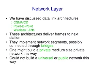
In-Building and Layer 2 • There is usually a correspondence between building separation and subnet separation • Switching inside a building • Routing between buildings • This will depend on the size of the network • Very small networks can get by with doing switching between buildings • Very large networks might need to do routing inside buildings
Layer 2 Concepts • Layer 2 protocols basically control access to a shared medium (copper, fiber, electro-magnetic waves) • Ethernet is the de-facto wired-standard today • Reasons: • Simple • Cheap • Manufacturers keep making it faster • Wireless (802.11a,b,g,n) is also Layer-2 technology.
Ethernet Functions • Source and Destination identification • MAC addresses • Detect and avoid frame collisions • Listen and wait for channel to be available • If collision occurs, wait a random period before retrying • This is called CASMA-CD: Carrier Sense Multiple Access with Collision Detection
Ethernet Frame • SFD = Start of Frame Delimiter • DA = Destination Address • SA = Source Address • CRC = Cyclick Redundancy Check
Evolution of Ethernet Topologies • Bus • Everybody on the same coaxial cable • Star • One central device connects every other node • First with hubs (repeated traffic) • Later with switches (bridged traffic) • Structured cabling for star topologies standardized
Switched Star Topology Benefits • It’s modular: • Independent wires for each end node • Independent traffic in each wire • A second layer of switches can be added to build a hierarchical network that extends the same two benefits above • ALWAYS DESIGN WITH MODULARITY IN MIND
Hub • Receives a frame on one port and sends it out every other port, always. • Collision domain is not reduced • Traffic ends up in places where it’s not needed
Hub Hub A frame sent by one node is always sent to every other node. Hubs are also called “repeaters” because they just “repeat” what they hear.
Switch • Learns the location of each node by looking at the source address of each incoming frame, and builds a forwarding table • Forwards each incoming frame to the port where the destination node is • Reduces the collision domain • Makes more efficient use of the wire • Nodes don’t waste time checking frames not destined to them
Switch Forwarding Table Switch B A
Switches and Broadcast • A switch broadcasts some frames: • When the destination address is not found in the table • When the frame is destined to the broadcast address (FF:FF:FF:FF:FF:FF) • When the frame is destined to a multicast ethernet address • So, switches do not reduce the broadcast domain!
Switch vs. Router • Routers more or less do with IP packets what switches do with Ethernet frames • A router looks at the IP packet destination and checks its routing table to decide where to forward the packet • Some differences: • IP packets travel inside ethernet frames • IP networks can be logically segmented into subnets • Switches do not usually know about IP, they only deal with Ethernet frames
Switch vs. Router • Routers do not forward Ethernet broadcasts. • Switches reduce the collision domain • Routers reduce the broadcast domain • This becomes really important when trying to design hierarchical, scalable networks that can grow sustainably R S S
Switch Switch Hub Hub Hub Hub Traffic Domains Router Collision Domain Broadcast Domain
Traffic Domains • Try to eliminate collision domains • Get rid of hubs! • Actually hubs are very rare today. • Try to keep your broadcast domain limited to no more than 250 simultaneously connected hosts • Segment your network using routers
Layer 2 Network Design Guidelines • Always connect hierarchically • If there are multiple switches in a building, use an aggregation switch • Locate the aggregation switch close to the building entry point (e.g. fiber panel) • Locate edge switches close to users (e.g. one per floor) • Max length for Cat 5 is 100 meters
Build Incrementally • Start small Fiber link to distribution switch Switch Hosts
Build Incrementally • As you have demand and money, grow like this: Aggreg. Switch Hosts
Build Incrementally • And keep growing within the same hierarchy: Aggreg. Switch Switch Hosts Hosts
Build Incrementally • At this point, you can also add a redundant aggregation switch: Aggreg. Aggreg. Switch Switch Hosts
Do not daisy-chain • Resist the temptation of doing this: ✗
Virtual LANs (VLANs) • Allow us to split switches into separate (virtual) switches • Only members of a VLAN can see that VLAN’s traffic • Inter-vlan traffic must go through a router
VLAN introduction • VLANs provide segmentation based on broadcast domains. • VLANs logically segment switched networks based on the functions, project teams, or applications of the organization regardless of the physical location or connections to the network. • All workstations and servers used by a particular workgroup share the same VLAN, regardless of the physical connection or location.
Local VLANs • 2 VLANs or more within a single switch • VLANs address scalability, security, and network management. Routers in VLAN topologies provide broadcast filtering, security, and traffic flow management. • Edge ports, where end nodes are connected, are configured as members of a VLAN • The switch behaves as several virtual switches, sending traffic only within VLAN members. • Switches may not bridge any traffic between VLANs, as this would violate the integrity of the VLAN broadcast domain. • Traffic should only be routed between VLANs.
Local VLANs Switch VLAN X VLAN Y Edge ports VLAN X nodes VLAN Y nodes
Broadcast domains with VLANs and routers 10.1.0.0/16 • Without VLANs, each group is on a different IP network and on a different switch. • Using VLANs. Switch is configured with the ports on the appropriate VLAN. Still, each group on a different IP network; however, they are all on the same switch. • What are the broadcast domains in each? 10.2.0.0/16 Without VLANs: 10.3.0.0/16 One link per VLAN or a single VLAN Trunk (later) 10.1.0.0/16 With VLANs 10.2.0.0/16 10.3.0.0/16
VLANs • Important notes on VLANs: • VLANs are assigned to switch ports. There is no “VLAN” assignment done on the host (usually). • In order for a host to be a part of that VLAN, it must be assigned an IP address that belongs to the proper subnet. Remember: VLAN = Subnet Two VLANs = Two subnets
VLANs ARP Request • VLANs separate broadcast domains!e.g. without VLAN the ARP would be seen on all subnets. • Assigning a host to the correct VLAN is a 2-step process: • Connect the host to the correct port on the switch. • Assign to the host the correct IP address depending on the VLAN membership Two VLANs = Two subnets
VLAN operation • As a device enters the network, it automatically assumes the VLAN membershipof the port to which it is attached. • The default VLAN for every port in the switch is VLAN 1 and cannot be deleted. (This statement does not give the whole story. More in the lab later for interested groups…) • All other ports on the switch may be reassigned to alternate VLANs.
VLANs across switches • Two switches can exchange traffic from one or more VLANs • Inter-switch links are configured as trunks, carrying frames from all or a subset of a switch’s VLANs • Each frame carries a tag that identifies which VLAN it belongs to
VLANs across switches • VLAN tagging is used when a single link needs to carry traffic for more than one VLAN. No VLAN Tagging VLAN Tagging
VLANs across switches Tagged Frames 802.1Q Trunk Trunk Port VLAN X VLAN Y VLAN X VLAN Y Edge Ports This is called “VLAN Trunking”
802.1Q • The IEEE standard that defines how ethernet frames should be tagged when moving across switch trunks • This means that switches from different vendors are able to exchange VLAN traffic.
Tagged vs. Untagged • Edge ports are not tagged, they are just “members” of a VLAN • You only need to tag frames in switch-to-switch links (trunks), when transporting multiple VLANs • A trunk can transport both tagged and untagged VLANs • As long as the two switches agree on how to handle those
VLANS increase complexity • You can no longer “just replace” a switch • Now you have VLAN configuration to maintain • Field technicians need more skills • You have to make sure that all the switch-to-switch trunks are carrying all the necessary VLANs • Need to keep in mind when adding/removing VLANs
Good reasons to use VLANs • You want to segment your network into multiple subnets, but can’t buy enough switches • Hide sensitive infrastructure like IP phones, building controls, etc. • Separate control traffic from user traffic • Restrict who can access your switch management address
Bad reasons to use VLANs • Because you can, and you feel cool • Because they will completely secure your hosts (or so you think) • Because they allow you to extend the same IP network over multiple separate buildings
Do not build “VLAN spaghetti” • Extending a VLAN to multiple buildings across trunk ports • Bad idea because: • Broadcast traffic is carried across all trunks from one end of the network to another • Broadcast storm can spread across the extent of the VLAN • Maintenance and troubleshooting nightmare
Configuring static VLANs • VLAN 1 is one of the factory-default VLANs. • Configure VLANs: • Switch#conf t • Switch(config)#interface vlan 10 • Switch(config-if)#ip address x.x.x.x m.m.m.m
Creating VLANs • Create the VLAN: Switch#vlan database Switch(vlan)#vlan vlan_number Switch(vlan)#exit • Assign ports to the VLAN (in configuration mode): Switch(config)#interface fastethernet 0/9 Switch(config-if)#switchport access vlan 10 • access– Denotes this port as an access port and not a trunk vlan 10 Default vlan 1 Default vlan 1
Verifying VLANs – show vlan-switch vlan 1 default vlan 2 vlan 3 show vlan-switch
show vlan-switch brief vlan 1 default vlan 2 vlan 3 show vlan-switch brief
Optional Command to add, delete, or modify VLANs. VLAN names, numbers, and VTP (VLAN Trunking Protocol) information can be entered which “may” affect other switches besides this one. (Not part of this module) This does not assign any VLANs to an interface. Switch#vlan database Switch(vlan)#? VLAN database editing buffer manipulation commands: abort Exit mode without applying the changes apply Apply current changes and bump revision number exit Apply changes, bump revision number, and exit mode no Negate a command or set its defaults reset Abandon current changes and reread current database show Show database information vlan Add, delete, or modify values associated with a single VLAN vtp Perform VTP administrative functions. vlan database commands