Network Layer
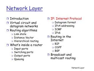
Network Layer. Dr. Yingwu Zhu. Introduction Datagram networks IP: Internet Protocol Datagram format IPv4 addressing ICMP What’s inside a router. Routing algorithms Link state Distance Vector Hierarchical routing Routing in the Internet RIP OSPF BGP Broadcast and multicast routing.


Network Layer
E N D
Presentation Transcript
Network Layer Dr. Yingwu Zhu
Introduction Datagram networks IP: Internet Protocol Datagram format IPv4 addressing ICMP What’s inside a router Routing algorithms Link state Distance Vector Hierarchical routing Routing in the Internet RIP OSPF BGP Broadcast and multicast routing Network Layer
transport segment from sending to receiving host on sending side encapsulates segments into datagrams on receiving side, delivers segments to transport layer network layer protocols in every host, router Router examines header fields in all IP datagrams passing through it network data link physical network data link physical network data link physical network data link physical network data link physical network data link physical network data link physical network data link physical application transport network data link physical application transport network data link physical Network layer
Key Network-Layer Functions • forwarding: move packets from router’s input to appropriate router output • routing: determine route taken by packets from source to dest. • Routing algorithms analogy: • routing: process of planning trip from source to dest • forwarding: process of getting through single interchange
routing algorithm local forwarding table header value output link 0100 0101 0111 1001 3 2 2 1 value in arriving packet’s header 1 0111 2 3 Interplay between routing and forwarding
Introduction Datagram networks IP: Internet Protocol Datagram format IPv4 addressing ICMP What’s inside a router Routing algorithms Link state Distance Vector Hierarchical routing Routing in the Internet RIP OSPF BGP Broadcast and multicast routing Network Layer
Connection-less service; no call setup at network layer routers: no state about end-to-end connections (why?) no network-level concept of “connection” packets forwarded using destination host address packets between same source-dest pair may take different paths application transport network data link physical application transport network data link physical Datagram networks 1. Send data 2. Receive data
Introduction Datagram networks IP: Internet Protocol Datagram format IPv4 addressing ICMP What’s inside a router Routing algorithms Link state Distance Vector Hierarchical routing Routing in the Internet RIP OSPF BGP Broadcast and multicast routing Network Layer
Host, router network layer functions: • ICMP protocol • error reporting • router “signaling” • IP protocol • addressing conventions • datagram format • packet handling conventions • Routing protocols • path selection • RIP, OSPF, BGP forwarding table The Internet Network layer Transport layer: TCP, UDP Network layer Link layer physical layer
The Internet Protocol (IP) Protocol Stack App Transport TCP / UDP Data Hdr TCP Segment Network IP Data Hdr IP Datagram Link
A B D H The Internet Protocol (IP) • Characteristics of IP • CONNECTIONLESS: mis-sequencing • UNRELIABLE: may drop packets… • BEST EFFORT: … but only if necessary • DATAGRAM: individually routed Source Destination R2 D H R1 R3 • Architecture • Links • Topology R4 Transparent
IP protocol version number 32 bits total datagram length (bytes) header length (bytes) type of service head. len ver length for fragmentation/ reassembly fragment offset “type” of data flgs 16-bit identifier max number remaining hops (decremented at each router) upper layer time to live Internet checksum 32 bit source IP address 32 bit destination IP address upper layer protocol to deliver payload to E.g. timestamp, record route taken, specify list of routers to visit. Options (if any) data (variable length, typically a TCP or UDP segment) IP datagram format 6 for TCP how much overhead with TCP? • 20 bytes of TCP • 20 bytes of IP • = 40 bytes + app layer overhead
Problem: A router may receive a packet larger than the maximum transmission unit (MTU) of the outgoing link. different link types, different MTUs Solution: large IP datagram divided (“fragmented”) within net one datagram becomes several datagrams “reassembled” only at final destination, why? IP header bits used to identify, order related fragments IP Fragmentation & Reassembly fragmentation: in: one large datagram out: 3 smaller datagrams reassembly E.g., Ethernet frames carry up to 1500 bytes, frames for some wide-area links carry no more than 576 bytes. (MTU: the max of data a link-layer frame can carry)
length =1500 length =1500 length =4000 length =1040 ID =x ID =x ID =x ID =x fragflag =0 fragflag =1 fragflag =1 fragflag =0 offset =0 offset =0 offset =370 offset =185 One large datagram becomes several smaller datagrams IP Fragmentation and Reassembly Example • 4000 byte datagram • MTU = 1500 bytes 1480 bytes in data field offset = 1480/8 Note: the offset value is specified in units of 8-byte chunks!!!
Fragmentation • Fragments are re-assembled by the destination host; not by intermediate routers. • To avoid fragmentation, hosts commonly use path MTU discovery to find the smallest MTU along the path. • Path MTU discovery involves sending various size datagrams until they do not require fragmentation along the path. • Most links use MTU>=1500bytes today. • Try: traceroute www.berkeley.edu 500–F andtraceroute www.berkeley.edu 1501 • -F: Set the "don't fragment" bit, return error it is too long • Bonus: Can you find a destination for which the path MTU < 1500 bytes?
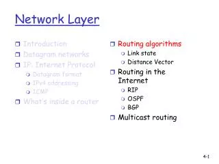
Introduction Virtual circuit and datagram networks What’s inside a router IP: Internet Protocol Datagram format IPv4 addressing ICMP IPv6 Routing algorithms Link state Distance Vector Hierarchical routing Routing in the Internet RIP OSPF BGP Broadcast and multicast routing Network Layer
IP Addresses • IP (Version 4) addresses are 32 bits long • Every interface has a unique IP address: • A computer might have two or more IP addresses • A router has many IP addresses • IP addresses are hierarchical • They contain a network ID and a host ID • E.g. SeattleU addresses start with: 172.17… • IP addresses are assigned statically or dynamically (e.g. DHCP) • IP (Version 6) addresses are 128 bits long
IP Addresses Originally there were 5 classes: 24 1 7 CLASS “A” Host-ID 0 Net ID 16 2 14 CLASS “B” Host-ID 10 Net ID 8 3 21 CLASS “C” Host-ID 110 Net ID 4 28 CLASS “D” 1110 Multicast Group ID 5 27 CLASS “E” 11110 Reserved A B C D 0 232-1
IP AddressesExamples • Class “A” address: www.mit.edu • 18.181.0.31 • (18<128 => Class A) • Class “B” address: www.seattleu.edu • 172.17.72.14 • (128<171<128+64 => Class B)
IP Addressing Problem: • Address classes were too “rigid”. For most organizations, Class C were too small and Class B too big. Led to inefficient use of address space, and a shortage of addresses. • Organizations with internal routers needed to have a separate (Class C) network ID for each link. • And then every other router in the Internet had to know about every network ID in every organization, which led to large address tables. • Small organizations wanted Class B in case they grew to more than 255 hosts. But there were only about 16,000 Class B network IDs.
IP Addressing Two solutions were introduced: • Subnetting within an organization to subdivide the organization’s network ID. • Classless Interdomain Routing (CIDR) in the Internet backbone was introduced in 1993 to provide more efficient and flexible use of IP address space. • CIDR is also known as “supernetting” because subnetting and CIDR are basically the same idea.
Subnetting 16 2 14 CLASS “B” e.g. Company Host-ID 10 Net ID 16 16 2 14 2 14 e.g. Site 0000 1111 Host-ID Host-ID 10 Net ID 10 Net ID Subnet ID (20) Subnet Host ID (12) Subnet ID (20) Subnet Host ID (12) 16 16 2 14 2 14 e.g. Dept Host-ID 10 Net ID 1111011011 Host-ID 10 Net ID 000000 Subnet ID (26) Subnet Host ID (6) Subnet ID (22) Subnet Host ID (10)
Subnetting • Subnetting is a form of hierarchical routing. • Subnets are usually represented via an address plus a subnet mask or “netmask”. • e.g. [zhuy@cs1 ~]$ /sbin/ifconfig eth0 eth0 Link encap:Ethernet HWaddr 00:21:9B:8F:64:6D inet addr:10.124.72.20 Bcast:10.124.72.255 Mask:255.255.255.0 • Netmask 255.255.255.0: the first 24 bits are the subnet ID, and the last 8 bits are the host ID. • Can also be represented by a “prefix + length”, e.g. 171.64.15.0/24, or just 171.64.15/24.
IP address: 32-bit identifier for host, router interface interface: connection between host/router and physical link router’s typically have multiple interfaces host typically has one interface IP addresses associated with each interface 223.1.1.2 223.1.2.1 223.1.3.27 223.1.3.1 223.1.3.2 223.1.2.2 IP Addressing 223.1.1.1 223.1.2.9 223.1.1.4 223.1.1.3 223.1.1.1 = 11011111 00000001 00000001 00000001 223 1 1 1
IP address: subnet part (high order bits) host part (low order bits) What’s a subnet ? device interfaces with same subnet part of IP address can physically reach each other without intervening router Subnets 223.1.1.1 223.1.2.1 223.1.1.2 223.1.2.9 223.1.1.4 223.1.2.2 223.1.1.3 223.1.3.27 subnet 223.1.3.2 223.1.3.1 network consisting of 3 subnets
Recipe To determine the subnets, detach each interface from its host or router, creating islands of isolated networks. Each isolated network is called a subnet. 223.1.1.0/24 223.1.2.0/24 223.1.3.0/24 Subnets Subnet mask: /24
How many? Subnets 223.1.1.2 223.1.1.1 223.1.1.4 223.1.1.3 223.1.7.0 223.1.9.2 223.1.9.1 223.1.7.1 223.1.8.1 223.1.8.0 223.1.2.6 223.1.3.27 223.1.2.1 223.1.2.2 223.1.3.1 223.1.3.2
142.12/19 Classless Interdomain Routing (CIDR)Addressing • The IP address space is broken into line segments. • Subnet portion of address of arbitrary length • Each line segment is described by a prefix. • A prefix is of the form x/y where x indicates the prefix of all addresses in the line segment, and y indicates the length of the segment. • e.g. The prefix 128.9/16 represents the line segment containing addresses in the range: 128.9.0.0 … 128.9.255.255. 128.9.0.0 65/8 128.9/16 0 232-1 216 Classful addressing: 8-bit segments for network portion CIDR: prefix/len, remove class distinction 128.9.16.14
128.9.19/24 128.9.25/24 128.9.16/20 128.9.176/20 Most specific route = “longest matching prefix” Classless Interdomain Routing (CIDR)Addressing 128.9/16 0 232-1 128.9.16.14
Classless Interdomain Routing (CIDR)Addressing Prefix aggregation: • If a service provider serves two organizations with prefixes, it can (sometimes) aggregate them to form a shorter prefix. Other routers can refer to this shorter prefix, and so reduce the size of their address table. • E.g. ISP serves 128.9.14.0/24 and 128.9.15.0/24, it can tell other routers to send it all packets belonging to the prefix 128.9.14.0/23. ISP Choice: • In principle, an organization can keep its prefix if it changes service providers.
Size of the Routing Table at the core of the Internet Source: http://www.cidr-report.org/
IP addresses: how to get one? Q: How does host get IP address? • hard-coded by system admin in a file • Wintel: control-panel->network->configuration->tcp/ip->properties • UNIX: /etc/rc.config • DHCP:Dynamic Host Configuration Protocol: dynamically get address from as server • “plug-and-play”
IP addresses: how to get one? Q: How does network get subnet part of IP addr? A: gets allocated portion of its provider ISP’s address space ISP's block 11001000 00010111 00010000 00000000 200.23.16.0/20 Organization 0 11001000 00010111 00010000 00000000 200.23.16.0/23 Organization 1 11001000 00010111 00010010 00000000 200.23.18.0/23 Organization 2 11001000 00010111 00010100 00000000 200.23.20.0/23 ... ….. …. …. Organization 7 11001000 00010111 00011110 00000000 200.23.30.0/23
200.23.16.0/23 200.23.18.0/23 200.23.30.0/23 200.23.20.0/23 . . . . . . Hierarchical addressing: route aggregation Hierarchical addressing allows efficient advertisement of routing information: Organization 0 Organization 1 “Send me anything with addresses beginning 200.23.16.0/20” Organization 2 Fly-By-Night-ISP Internet Organization 7 “Send me anything with addresses beginning 199.31.0.0/16” ISPs-R-Us
200.23.16.0/23 200.23.18.0/23 200.23.30.0/23 200.23.20.0/23 . . . . . . Hierarchical addressing: more specific routes ISPs-R-Us has a more specific route to Organization 1 Organization 0 “Send me anything with addresses beginning 200.23.16.0/20” Organization 2 Fly-By-Night-ISP Internet Organization 7 “Send me anything with addresses beginning 199.31.0.0/16 or 200.23.18.0/23” ISPs-R-Us Organization 1 Longest prefix match
IP addressing: the last word... Q: How does an ISP get block of addresses? A: ICANN: Internet Corporation for Assigned Names and Numbers • allocates addresses • manages DNS • assigns domain names, resolves disputes
NAT: Network Address Translation rest of Internet local network (e.g., home network) 10.0.0/24 10.0.0.1 10.0.0.4 10.0.0.2 138.76.29.7 10.0.0.3 Datagrams with source or destination in this network have 10.0.0/24 address for source, destination (as usual) All datagrams leaving local network have same single source NAT IP address: 138.76.29.7, different source port numbers
NAT: Network Address Translation • Motivation: local network uses just one IP address as far as outside world is concerned: • no need to be allocated range of addresses from ISP: - just one IP address is used for all devices • can change addresses of devices in local network without notifying outside world • can change ISP without changing addresses of devices in local network • devices inside local net not explicitly addressable, visible by outside world (a security plus).
NAT: Network Address Translation Implementation: NAT router must: • outgoing datagrams:replace (source IP address, port #) of every outgoing datagram to (NAT IP address, new port #) . . . remote clients/servers will respond using (NAT IP address, new port #) as destination addr. • remember (in NAT translation table) every (source IP address, port #) to (NAT IP address, new port #) translation pair • incoming datagrams:replace (NAT IP address, new port #) in dest fields of every incoming datagram with corresponding (source IP address, port #) stored in NAT table
3 1 2 4 S: 10.0.0.1, 3345 D: 128.119.40.186, 80 S: 138.76.29.7, 5001 D: 128.119.40.186, 80 1: host 10.0.0.1 sends datagram to 128.119.40.186, 80 2: NAT router changes datagram source addr from 10.0.0.1, 3345 to 138.76.29.7, 5001, updates table S: 128.119.40.186, 80 D: 10.0.0.1, 3345 S: 128.119.40.186, 80 D: 138.76.29.7, 5001 NAT: Network Address Translation NAT translation table WAN side addr LAN side addr 138.76.29.7, 5001 10.0.0.1, 3345 …… …… 10.0.0.1 10.0.0.4 10.0.0.2 138.76.29.7 10.0.0.3 4: NAT router changes datagram dest addr from 138.76.29.7, 5001 to 10.0.0.1, 3345 3: Reply arrives dest. address: 138.76.29.7, 5001
NAT: Network Address Translation • 16-bit port-number field: • 60,000 simultaneous connections with a single LAN-side address! • NAT is controversial: • routers should only process up to layer 3 • violates end-to-end argument • NAT possibility must be taken into account by app designers, eg, P2P applications • address shortage should instead be solved by IPv6
Introduction Virtual circuit and datagram networks What’s inside a router IP: Internet Protocol Datagram format IPv4 addressing ICMP IPv6 Routing algorithms Link state Distance Vector Hierarchical routing Routing in the Internet RIP OSPF BGP Broadcast and multicast routing Network Layer
used by hosts & routers to communicate network-level information error reporting: unreachable host, network, port, protocol echo request/reply (used by ping) network-layer “above” IP: ICMP msgs carried in IP datagrams ICMP message: type, code plus first 8 bytes of IP datagram causing error ICMP: Internet Control Message Protocol TypeCodedescription 0 0 echo reply (ping) 3 0 dest. network unreachable 3 1 dest host unreachable 3 2 dest protocol unreachable 3 3 dest port unreachable 3 6 dest network unknown 3 7 dest host unknown 4 0 source quench (congestion control - not used) 8 0 echo request (ping) 9 0 route advertisement 10 0 router discovery 11 0 TTL expired 12 0 bad IP header
An aside:Error Reporting (ICMP) and traceroute Internet Control Message Protocol: • Used by a router/end-host to report some types of error: • E.g. Destination Unreachable: packet can’t be forwarded to/towards its destination. • E.g. Time Exceeded: TTL reached zero, or fragment didn’t arrive in time. Traceroute uses this error to its advantage. • An ICMP message is an IP datagram, and is sent back to the source of the packet that caused the error.
Source sends series of UDP segments to dest First has TTL =1 Second has TTL=2, etc. Unlikely port number When nth datagram arrives to nth router: Router discards datagram And sends to source an ICMP message (type 11, code 0) Message includes name of router& IP address When ICMP message arrives, source calculates RTT Traceroute does this 3 times Stopping criterion UDP segment eventually arrives at destination host Destination returns ICMP “host unreachable” packet (type 3, code 3) When source gets this ICMP, stops. Traceroute and ICMP It would be fun if you design a traceroute tool on your own!
Introduction Datagram networks IP: Internet Protocol Datagram format IPv4 addressing ICMP What’s inside a router Routing algorithms Link state Distance Vector Hierarchical routing Routing in the Internet RIP OSPF BGP Broadcast and multicast routing Network Layer
Router Architecture Overview Two key router functions: • run routing algorithms/protocol (RIP, OSPF, BGP) • forwarding datagrams from incoming to outgoing link
Input Port Functions Decentralized switching: • given datagram dest., lookup output port using forwarding table in input port memory • goal: complete input port processing at ‘line speed’ • queuing: if datagrams arrive faster than forwarding rate into switch fabric Physical layer: bit-level reception Data link layer: e.g., Ethernet
Memory Input Port Output Port System Bus Switching Via Memory First generation routers: • traditional computers with switching under direct control of CPU • packet copied to system’s memory • speed limited by memory bandwidth (2 bus crossings per datagram)