Network Layer Essentials: IP, Routing & Subnets
Explore virtual circuit & datagram networks, routing algorithms, IP addressing, ICMP, IPv6, subnetting, routing protocols like OSPF & BGP, network layers, and understanding the components inside a router in this comprehensive guide.

Network Layer Essentials: IP, Routing & Subnets
E N D
Presentation Transcript
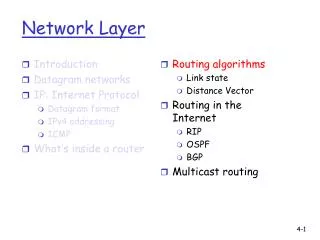
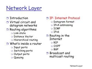
Introduction Virtual circuit and datagram networks Routing algorithms Link state Distance Vector Hierarchical routing What’s inside a router Input ports Switching ports Output ports Queuing IP: Internet Protocol Datagram format IPv4 addressing ICMP IPv6 Routing in the Internet RIP OSPF BGP Broadcast and multicast routing Network Layer Network Layer
Host, router network layer functions: • ICMP protocol • error reporting • router “signaling” • IP protocol • addressing conventions • datagram format • packet handling conventions • Routing protocols • path selection • RIP, OSPF, BGP forwarding table The Internet Network layer Transport layer: TCP, UDP Network layer Link layer physical layer Network Layer
Introduction Virtual circuit and datagram networks Routing algorithms Link state Distance Vector Hierarchical routing What’s inside a router Input ports Switching ports Output ports Queuing IP: Internet Protocol Datagram format IPv4 addressing ICMP IPv6 Routing in the Internet RIP OSPF BGP Broadcast and multicast routing Network Layer Network Layer
IP protocol version number 32 bits total datagram length (bytes) header length (bytes) type of service head. len ver length for fragmentation/ reassembly fragment offset “type” of data flgs 16-bit identifier max number remaining hops (decremented at each router) upper layer time to live Internet checksum 32 bit source IP address 32 bit destination IP address upper layer protocol to deliver payload to E.g. timestamp, record route taken, specify list of routers to visit. Options (if any) data (variable length, typically a TCP or UDP segment) IP datagram format how much overhead with TCP? • 20 bytes of TCP • 20 bytes of IP • = 40 bytes + app layer overhead Network Layer
network links have MTU (max.transfer size) - largest possible link-level frame. different link types, different MTUs large IP datagram divided (“fragmented”) within net one datagram becomes several datagrams “reassembled” only at final destination IP header bits used to identify, order related fragments IP Fragmentation & Reassembly fragmentation: in: one large datagram out: 3 smaller datagrams reassembly Network Layer
length =1500 length =1040 length =1500 length =4000 ID =x ID =x ID =x ID =x fragflag =0 fragflag =0 fragflag =1 fragflag =1 offset =0 offset =185 offset =0 offset =370 One large datagram becomes several smaller datagrams IP Fragmentation and Reassembly Example • 4000 byte datagram • MTU = 1500 bytes 1480 bytes in data field offset = 1480/8 Network Layer
Introduction Virtual circuit and datagram networks Routing algorithms Link state Distance Vector Hierarchical routing What’s inside a router Input ports Switching ports Output ports Queuing IP: Internet Protocol Datagram format IPv4 addressing ICMP IPv6 Routing in the Internet RIP OSPF BGP Broadcast and multicast routing Network Layer Network Layer
IP address: 32-bit identifier for host, router interface interface: connection between host/router and physical link router’s typically have multiple interfaces host typically has one interface IP addresses associated with each interface 223.1.1.2 223.1.2.2 223.1.2.1 223.1.3.2 223.1.3.1 223.1.3.27 IP Addressing: introduction 223.1.1.1 223.1.2.9 223.1.1.4 223.1.1.3 223.1.1.1 = 11011111 00000001 00000001 00000001 223 1 1 1 Network Layer
IP address: subnet part (high order bits) host part (low order bits) What’s a subnet ? device interfaces with same subnet part of IP address can physically reach each other without intervening router Subnets 223.1.1.1 223.1.2.1 223.1.1.2 223.1.2.9 223.1.1.4 223.1.2.2 223.1.1.3 223.1.3.27 subnet 223.1.3.2 223.1.3.1 network consisting of 3 subnets Network Layer
Recipe To determine the subnets, detach each interface from its host or router, creating islands of isolated networks. Each isolated network is called a subnet. 223.1.1.0/24 223.1.2.0/24 223.1.3.0/24 Subnets Subnet mask: /24 Network Layer
How many? Subnets 223.1.1.2 223.1.1.1 223.1.1.4 223.1.1.3 223.1.7.0 223.1.9.2 223.1.9.1 223.1.7.1 223.1.8.1 223.1.8.0 223.1.2.6 223.1.3.27 223.1.2.1 223.1.2.2 223.1.3.1 223.1.3.2 Network Layer
host part subnet part 11001000 0001011100010000 00000000 200.23.16.0/23 IP addressing: CIDR CIDR:Classless InterDomain Routing • subnet portion of address of arbitrary length • address format: a.b.c.d/x, where x is # bits in subnet portion of address Network Layer
IP addresses: how to get one? Q: How does host get IP address? • hard-coded by system admin in a file • Wintel: control-panel->network->configuration->tcp/ip->properties • UNIX: /etc/rc.config • DHCP:Dynamic Host Configuration Protocol: dynamically get address from as server • “plug-and-play” (more in next chapter) Network Layer
IP addresses: how to get one? Q: How does network get subnet part of IP addr? A: gets allocated portion of its provider ISP’s address space ISP's block 11001000 00010111 00010000 00000000 200.23.16.0/20 Organization 0 11001000 00010111 00010000 00000000 200.23.16.0/23 Organization 1 11001000 00010111 00010010 00000000 200.23.18.0/23 Organization 2 11001000 00010111 00010100 00000000 200.23.20.0/23 ... ….. …. …. Organization 7 11001000 00010111 00011110 00000000 200.23.30.0/23 Network Layer
200.23.16.0/23 200.23.18.0/23 200.23.30.0/23 200.23.20.0/23 . . . . . . Hierarchical addressing: route aggregation Hierarchical addressing allows efficient advertisement of routing information: Organization 0 Organization 1 “Send me anything with addresses beginning 200.23.16.0/20” Organization 2 Fly-By-Night-ISP Internet Organization 7 “Send me anything with addresses beginning 199.31.0.0/16” ISPs-R-Us Network Layer
200.23.16.0/23 200.23.18.0/23 200.23.30.0/23 200.23.20.0/23 . . . . . . Hierarchical addressing: more specific routes ISPs-R-Us has a more specific route to Organization 1 Organization 0 “Send me anything with addresses beginning 200.23.16.0/20” Organization 2 Fly-By-Night-ISP Internet Organization 7 “Send me anything with addresses beginning 199.31.0.0/16 or 200.23.18.0/23” ISPs-R-Us Organization 1 Network Layer
IP addressing: the last word... Q: How does an ISP get block of addresses? A: ICANN: Internet Corporation for Assigned Names and Numbers • allocates addresses • manages DNS • assigns domain names, resolves disputes Network Layer
Private Addresses • 10.0.0.0/8 • 172.16.0.0-172.31.0.0/12 • 192.168.0.0/16 Network Layer
Introduction Virtual circuit and datagram networks Routing algorithms Link state Distance Vector Hierarchical routing What’s inside a router Input ports Switching ports Output ports Queuing IP: Internet Protocol Datagram format IPv4 addressing ICMP IPv6 Routing in the Internet RIP OSPF BGP Broadcast and multicast routing Network Layer Network Layer
used by hosts & routers to communicate network-level information error reporting: unreachable host, network, port, protocol echo request/reply (used by ping) network-layer “above” IP: ICMP msgs carried in IP datagrams ICMP message: type, code plus first 8 bytes of IP datagram causing error ICMP: Internet Control Message Protocol TypeCodedescription 0 0 echo reply (ping) 3 0 dest. network unreachable 3 1 dest host unreachable 3 2 dest protocol unreachable 3 3 dest port unreachable 3 6 dest network unknown 3 7 dest host unknown 4 0 source quench (congestion control - not used) 8 0 echo request (ping) 9 0 route advertisement 10 0 router discovery 11 0 TTL expired 12 0 bad IP header Network Layer
Source sends series of UDP segments to dest First has TTL =1 Second has TTL=2, etc. Unlikely port number When nth datagram arrives to nth router: Router discards datagram And sends to source an ICMP message (type 11, code 0) Message includes name of router& IP address When ICMP message arrives, source calculates RTT Traceroute does this 3 times Stopping criterion UDP segment eventually arrives at destination host Destination returns ICMP “host unreachable” packet (type 3, code 3) When source gets this ICMP, stops. Traceroute and ICMP Network Layer
Introduction Virtual circuit and datagram networks Routing algorithms Link state Distance Vector Hierarchical routing What’s inside a router Input ports Switching ports Output ports Queuing IP: Internet Protocol Datagram format IPv4 addressing ICMP IPv6 Routing in the Internet RIP OSPF BGP Broadcast and multicast routing Network Layer Network Layer
IPv6 • Initial motivation:32-bit address space soon to be completely allocated. • Additional motivation: • header format helps speed processing/forwarding • header changes to facilitate QoS IPv6 datagram format: • fixed-length 40 byte header • no fragmentation allowed Network Layer
IPv6 Header (Cont) Priority: identify priority among datagrams in flow Flow Label: identify datagrams in same “flow.” (concept of“flow” not well defined). Next header: identify upper layer protocol for data Network Layer
Other Changes from IPv4 • Checksum:removed entirely to reduce processing time at each hop • Options: allowed, but outside of header, indicated by “Next Header” field • ICMPv6: new version of ICMP • additional message types, e.g. “Packet Too Big” • multicast group management functions Network Layer
Transition From IPv4 To IPv6 • Not all routers can be upgraded simultaneous • no “flag days” • How will the network operate with mixed IPv4 and IPv6 routers? • Tunneling: IPv6 carried as payload in IPv4 datagram among IPv4 routers Network Layer
F A B E F E B A tunnel Logical view: IPv6 IPv6 IPv6 IPv6 Physical view: IPv6 IPv6 IPv6 IPv6 IPv4 IPv4 Tunneling Network Layer
Flow: X Src: A Dest: F data Flow: X Src: A Dest: F data Flow: X Src: A Dest: F data Flow: X Src: A Dest: F data A B E F F A B E C D Src:B Dest: E Src:B Dest: E Tunneling tunnel Logical view: IPv6 IPv6 IPv6 IPv6 Physical view: IPv6 IPv6 IPv6 IPv6 IPv4 IPv4 A-to-B: IPv6 E-to-F: IPv6 B-to-C: IPv6 inside IPv4 B-to-C: IPv6 inside IPv4 Network Layer
Introduction Virtual circuit and datagram networks Routing algorithms Link state Distance Vector Hierarchical routing What’s inside a router Input ports Switching ports Output ports Queuing IP: Internet Protocol Datagram format IPv4 addressing ICMP IPv6 Routing in the Internet RIP OSPF BGP Broadcast and multicast routing Network Layer Network Layer
Intra-AS Routing • Also known as Interior Gateway Protocols (IGP) • Most common Intra-AS routing protocols: • RIP: Routing Information Protocol • OSPF: Open Shortest Path First • IGRP: Interior Gateway Routing Protocol (Cisco proprietary) Network Layer
Introduction Virtual circuit and datagram networks Routing algorithms Link state Distance Vector Hierarchical routing What’s inside a router Input ports Switching ports Output ports Queuing IP: Internet Protocol Datagram format IPv4 addressing ICMP IPv6 Routing in the Internet RIP OSPF BGP Broadcast and multicast routing Network Layer Network Layer
u v destinationhops u 1 v 2 w 2 x 3 y 3 z 2 w x z y C A D B RIP ( Routing Information Protocol) • Distance vector algorithm • Included in BSD-UNIX Distribution in 1982 • Distance metric: # of hops (max = 15 hops) From router A to subsets: Network Layer
RIP advertisements • Distance vectors: exchanged among neighbors every 30 sec via Response Message (also called advertisement) • Each advertisement: list of up to 25 destination nets within AS Network Layer
RIP: Example z w x y A D B C Destination Network Next Router Num. of hops to dest. w A 2 y B 2 z B 7 x -- 1 …. …. .... Routing table in D Network Layer
z w x y A D B C RIP: Example Dest Next hops w - 1 x - 1 z C 4 …. … ... Advertisement from A to D Destination Network Next Router Num. of hops to dest. w A 2 y B 2 z B A 7 5 x -- 1 …. …. .... Routing table in D Network Layer
RIP: Link Failure and Recovery If no advertisement heard after 180 sec --> neighbor/link declared dead • routes via neighbor invalidated • new advertisements sent to neighbors • neighbors in turn send out new advertisements (if tables changed) • link failure info quickly propagates to entire net • poison reverse used to prevent ping-pong loops (infinite distance = 16 hops) Network Layer
routed routed RIP Table processing • RIP routing tables managed by application-level process called route-d (daemon) • advertisements sent in UDP packets, periodically repeated Transprt (UDP) Transprt (UDP) network forwarding (IP) table network (IP) forwarding table link link physical physical Network Layer
Introduction Virtual circuit and datagram networks Routing algorithms Link state Distance Vector Hierarchical routing What’s inside a router Input ports Switching ports Output ports Queuing IP: Internet Protocol Datagram format IPv4 addressing ICMP IPv6 Routing in the Internet RIP OSPF BGP Broadcast and multicast routing Network Layer Network Layer
OSPF (Open Shortest Path First) • “open”: publicly available • Uses Link State algorithm • LS packet dissemination • Topology map at each node • Route computation using Dijkstra’s algorithm • OSPF advertisement carries one entry per neighbor router • Advertisements disseminated to entire AS (via flooding) • Carried in OSPF messages directly over IP (rather than TCP or UDP Network Layer
OSPF “advanced” features (not in RIP) • Security: all OSPF messages authenticated (to prevent malicious intrusion) • Multiple same-cost paths allowed (only one path in RIP) • For each link, multiple cost metrics for different TOS (e.g., satellite link cost set “low” for best effort; high for real time) • Integrated uni- and multicast support: • Multicast OSPF (MOSPF) uses same topology data base as OSPF • Hierarchical OSPF in large domains. Network Layer
Hierarchical OSPF Network Layer
Hierarchical OSPF • Two-level hierarchy: local area, backbone. • Link-state advertisements only in area • each nodes has detailed area topology; only know direction (shortest path) to nets in other areas. • Area border routers:“summarize” distances to nets in own area, advertise to other Area Border routers. • Backbone routers: run OSPF routing limited to backbone. • Boundary routers: connect to other AS’s. Network Layer
Introduction Virtual circuit and datagram networks Routing algorithms Link state Distance Vector Hierarchical routing What’s inside a router Input ports Switching ports Output ports Queuing IP: Internet Protocol Datagram format IPv4 addressing ICMP IPv6 Routing in the Internet RIP OSPF BGP Broadcast and multicast routing Network Layer Network Layer
Internet inter-AS routing: BGP • BGP (Border Gateway Protocol):the de facto standard • BGP provides each AS a means to: • Obtain subnet reachability information from neighboring ASs. • Propagate the reachability information to all routers internal to the AS. • Determine “good” routes to subnets based on reachability information and policy. • Allows a subnet to advertise its existence to rest of the Internet: “I am here” Network Layer
3a 3b 2a AS3 AS2 1a 2c AS1 2b eBGP session 3c 1b 1d 1c iBGP session BGP basics • Pairs of routers (BGP peers) exchange routing info over semi-permanent TCP conctns: BGP sessions • Note that BGP sessions do not correspond to physical links. • When AS2 advertises a prefix to AS1, AS2 is promising it will forward any datagrams destined to that prefix towards the prefix. • AS2 can aggregate prefixes in its advertisement Network Layer
eBGP and iBGP • eBGP is BGP between two ASes • Advertises prefixes to other ASes • Implements routing policy, (whether or not re-advertise prefixes received from BGP peers) • eBGP peers are directly connected • iBGP • Advertises some or all prefixes learnt from eBGP • Advertises ISP’s customer prefixes (For example a network that is recently allocated to some customer) • These are not directly connected but form a fully connected logical graph Network Layer
3a 3b 2a AS3 AS2 1a 2c AS1 2b eBGP session 3c 1b 1d 1c iBGP session Distributing reachability info • With eBGP session between 3a and 1c, AS3 sends prefix reachability info to AS1. • 1c can then use iBGP do distribute this new prefix reach info to all routers in AS1 • 1b can then re-advertise the new reach info to AS2 over the 1b-to-2a eBGP session • When router learns about a new prefix, it creates an entry for the prefix in its forwarding table. Network Layer
Path attributes & BGP routes • When advertising a prefix, advert includes BGP attributes. • prefix + attributes = “route” • Two important attributes: • AS-PATH: contains the ASs through which the advert for the prefix passed: AS 67 AS 17 • NEXT-HOP: Indicates the specific internal-AS router to next-hop AS. (There may be multiple links from current AS to next-hop-AS.) • When gateway router receives route advert, uses import policy to accept/decline. Network Layer
eBGP Next Hop Network Layer
BGP route selection • Router may learn about more than 1 route to some prefix. Router must select route. • Elimination rules: • Local preference value attribute: policy decision • Shortest AS-PATH • Closest NEXT-HOP router: hot potato routing • Additional criteria Network Layer