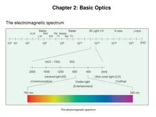
Basic Optics: Essentials of Spectral Analysis and Emission Processes
Explore the fundamentals of optics, phase angles, spectral linewidths, molecular bands, radiation sources, and continuum emissions. Learn about coherence, blackbody radiation, and stimulated emission in a comprehensive guide.


Basic Optics: Essentials of Spectral Analysis and Emission Processes
E N D
Presentation Transcript
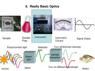
6. Really Basic Optics Instrument Sample Prep Instrument Out put Sample Signal (Data) Turn off/diminish intensity Polychromatic light Selected light Sample interaction Select light Turn on different wavelength select source detect
Really Basic Optics Key definitions Phase angle Atomic lines vs molecular bands Atomic Line widths (effective; natural) Doppler broadening Molecular bands Continuum sources Blackbody radiators Coherent vs incoherent radiation
6. Really Basic Optics A Sin=opp/hyp y /2 3/2 2 90o phase angle /2 radian phase angle
Emission of Photons Electromagnetic radiation is emitted when electrons relax from excited states. A photon of the energy equivalent to the difference in electronic states Is emitted Ehi e Elo Frequency 1/s
Really Basic Optics Key definitions Phase angle Atomic lines vs molecular bands Atomic Line widths (effective; natural) Doppler broadening Molecular bands Continuum sources Blackbody radiators Coherent vs incoherent radiation
Natural Line Widths frequency • Line broadens due • Uncertainty • Doppler effect • Pressure • Electric and magnetic fields Lifetime of an excited state is typically 1x10⁻⁸ s
Example: 253.7 nm Typical natural line widths are 10-5 nm
Line broadens due • Uncertainty • Doppler effect • Pressure • Electric and magnetic fields
Line broadens due • Uncertainty • Doppler effect • Pressure • Electric and magnetic fields The lifetime of a spectral event is 1x10⁻⁸ s When an excited state atom is hit with another high energy atom energy is transferred which changes the energy of the excited state and, hence, the energy of the photon emitted. This results in linewidth broadening. The broadening is Lorentzian in shape. We use pressure broadening On purpose to get a large Line width in AA for some Forms of background correction FWHM = full width half maximum o is the peak “center” in frequency units
Line spectra – occur when radiating species are atomic particles which Experience no near neighbor interactions • Line broadens due • Uncertainty • Doppler effect • Pressure • Electric and magnetic fields Line events Can lie on top Of band events Overlapping line spectra lead to band emission
Continuum emission – an extreme example of electric and magnetic effects on broadening of multiple wavelengths High temperature solids emit Black Body Radiation many over lapping line and band emissions influenced by near neighbors
Stefan-Boltzmann Law Planck’s Blackbody Law = Energy density of radiation h= Planck’s constant C= speed of light k= Boltzmann constant T=Temperature in Kelvin = frequency Wien’s Law • As ↓(until effect of exp takes over) • As T,exp↓,
Really Basic Optics Key definitions Phase angle Atomic lines vs molecular bands Atomic Line widths (effective; natural) Doppler broadening Molecular bands Continuum sources Blackbody radiators Coherent vs incoherent radiation
Incoherent radiation The Multitude of emitters, even if they emit The same frequency, do not emit at the Same time A B Frequency,, is the Same but wave from particle B lags behind A by the Phase angle
END: Key Definitions Begin Using Constructive and Destructive Interference patterns based on phase lag By manipulating the path length can cause an originally coherent beam (all in phase, same frequency) to come out of phase can accomplish Many of the tasks we need to control light for our instruments • Constructive/Destructive interference • Laser • FT instrument • Can be used to obtain information about distances • Interference filter. • Can be used to select wavelengths
More Intense Radiation can be obtained by Coherent Radiation Lasers Beam exiting the cavity is in phase (Coherent) and therefore enhanced In amplitude
Argument on the size of signals that follows is from Atkins, Phys. Chem. p. 459, 6th Ed Is the energy density of radiation already present at the frequency of the transition N* and No are the populations of upper state and lower states Stimulated Emission Light Amplification by Stimulated Emission of Radiation Photons can stimulate Emission just as much As they can stimulate Absorption (idea behind LASERs Stimulated Emission) * o The rate of stimulated event is described by : Where w =rate of stimulated emission or absorption The more perturbing photons the greater the Stimulated emission B= empirical constant known as the Einstein coefficient for stimulated absorption or emission
can be described by the Planck equation for black body radiation at some T frequency In order to measure absorption it is required that the Rate of stimulated absorption is greater than the Rate of stimulated emission If the populations of * and o are the same the net absorption is zero as a photon is Absorbed and one is emitted
Need to get a larger population in the excited state Compared to the ground state (population inversion) Degeneracies of the different energy levels Special types of materials have larger excited state degeneracies Which allow for the formation of the excited state population inversion Serves to “trap” electrons in the excited State, which allows for a population inversion E pump
Constructive/Destructive interference • Laser • FT instrument • Can be used to select wavelengths • Can be used to obtain information about distances • Holographic Interference filter. Radiation not along the Path is lost mirror mirror • Stimulated emission • Single phase • Along same path • =Constructive Interference • Coherent radiation Multiple directions, Multiple phase lags Incoherent radiation
FTIR Instrument • Constructive/Destructive interference • Laser • FT instrument • Can be used to select wavelengths • Can be used to obtain information about distances • Holographic Interference filter.
Time Domain: 2 frequencies 1 “beat” cycle
B Fixed mirror A C Moving mirror Beam splitter IR source detector Constructive interference occurs when
-2 -1 +1 0
INTERFEROGRAMS Remember that: Frequency of light
An interferometer detects a periodic wave with a frequency of 1000 Hz when moving at a velocity of 1 mm/s. What is the frequency of light impinging on the detector?
No need to SELECT Wavelength by using Mirror, fiber optics, Gratings, etc.
FOURIER TRANSFORMS Advantages • Jaquinot or through-put • little photon loss; little loss of source intensity • Large number of wavelengths allows for ensemble averaging • (waveform averaging) 3. This leads to Fellget or multiplex advantage multiple spectra in little time implies?
DIFFRACTION Huygen’s principle = individual propagating waves combine to form a new wave front • Constructive/Destructive interference • Laser • FT instrument • Can be used to select wavelengths • Can be used to obtain information about distances • Holographic Interference filter. Can get coherent radiation if the slit is narrow enough. Coherent = all in one phase
June 19, 2008, Iowa Flood Katrina Levee break
D d B F’ E W O L F C From which we conclude
D The complete equation for a slit is d B E W L b=W/2 Width of the line depends upon The slit width!! Therefore resolution depends On slit width Also “see” This spectra “leak” of Our hard won intensity
The base (I=0) occurs whenever sinβ =0 Which occurs when The smaller the Slit width the Smaller The line width, Which leads To greater Spectral Resolution Remember R is Inversely proportional To the width of The Gaussian base
SLIT IMAGE Slit A 1 2 3 B Position number 1 2 3 4 5 Image When edge AB at Detector Sees Position 1 0% power Position 2 50% power Position 3 100% power Position 4 50% power Position 5 0 % power Detector output: Triangle results when Effective bandpass = image To resolve two images that are ∆ apart requires Implies want a narrower slit
Essentially, Narrow slit widths Are generally better
GRATINGS GratingsGroves/mm UV/Vis 300/2000 IR 10/20 • Points: • Master grating formed by diamond tip under ground • Or more recently formed from holographic processes • Copy gratings formed from resins
+ - q q
EXAMPLE Calculate for a grating which has i=45 2000 groves per mm • Get d 2) Use grating equation to solve for
Czerny-Turner construction 440.3 220.1 146.8 88 73 All come through Multiple wavelengths Are observed At a single angle Of reflection!! You get light of 674.9 nm ½; 1/3; 1/4; 1/5; etc.
Physical Dimensions: 89.1 mm x 63.3 mm x 34.4 mm Weight: 190 grams Detector: Sony ILX511 linear silicon CCD array Detector range: 200-1100 nm Pixels: 2048 pixels Pixel size: 14 μm x 200 μm Pixel well depth: ~62,500 electrons Sensitivity: 75 photons/count at 400 nm; 41 photons/count at 600 nm Design: f/4, Symmetrical crossed Czerny-Turner Focal length: 42 mm input; 68 mm output Entrance aperture: 5, 10, 25, 50, 100 or 200 µm wide slits or fiber (no slit) Grating options: 14 different gratings, UV through Shortwave NIR Detector collection lens option: Yes, L2 OFLV filter options: OFLV-200-850; OFLV-350-1000 Other bench filter options: Longpass OF-1 filters Collimating and focusing mirrors: Standard or SAG+ UV enhanced window: Yes, UV2 Fiber optic connector: SMA 905 to 0.22 numerical aperture single-strand optical fiber Spectroscopic Wavelength range: Grating dependent Optical resolution: ~0.3-10.0 nm FWHM Signal-to-noise ratio: 250:1 (at full signal) A/D resolution: 12 bit Dark noise: 3.2 RMS counts Dynamic range: 2 x 10^8 (system); 1300:1 for a single acquisition Integration time: 3 ms to 65 seconds Stray light: <0.05% at 600 nm; <0.10% at 435 nm Corrected linearity: >99.8% Electronics Power consumption: 90 mA @ 5 VDC Data transfer speed: Full scans to memory every 13 ms with USB 2.0 or 1.1 port, 300 ms with serial port Czerny-Turner construction
Ocean Optics For fluorescence lab 440.3 220.1 146.8 88 73 All come through Monochromator we looked inside 440.3 Only Hit grating first Time to get Hit grating second time 440.3 220.1 146.8 88 73 All come through 220.1 nm
Another way to look at it is to say We Lose some of the light Not all of it ends up at the intended angle of reflection Light of 100 Nm shows up At -30.4 AND -17.88 And -6.1 And 5.3 Etc.
GRATING DISPERSION D-1 = Reciprocal linear dispersion Where n= order F = focal length d= distance/groove POINT = linear dispersion
What is (are) the wavelength(s) transmitted at 45o reflected AND incident light for a grating of 4000 groves/mm?
RESOLUTION The larger R the greater the spread between the two wavelengths, normalized by The wavelength region Where n = order and N = total grooves exposed to light