Download
1 / 48
490 likes | 783 Vues
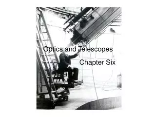
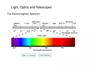
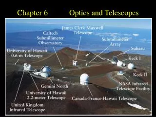
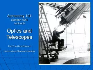
6. Optics and Telescopes. Refracting telescopes Reflecting telescopes Image degradation Imaging systems Spectrographs Non-optical telescopes Orbiting telescopes. Parallel Rays From Distant Objects. Refracting Telescopes. A lens is the primary image-forming tool

E N D
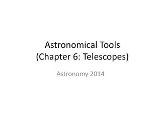
6. Optics and Telescopes • Refracting telescopes • Reflecting telescopes • Image degradation • Imaging systems • Spectrographs • Non-optical telescopes • Orbiting telescopes
Refracting Telescopes • A lens is the primary image-forming tool • Other lenses and/or mirrors may also be used • Basic physical process • Refraction • EMR bends due to speed differences in different media • Basic benefits • Very high contrast of resulting image • Basic problems • Severe practical limits on the size of the primary • Lenses cannot be mechanically supported from behind • Chromatic aberration • Different wavelengths refract by different amounts • Basic solution • Achromatic lenses
Refracting Telescope Designs • Convex primary lens & convex eyepiece lens • Inverted image Astronomical telescopes • Convex primary lens & concave eyepiece lens • Upright image Terrestrial telescopes
Chromatic Aberration In Lenses Simple lens Achromatic lens Only one lens Two or more lenses 1 1 2
Reflecting Telescopes • A mirror is the primary image-forming tool • Other mirrors and/or lenses may also be used • Basic physical process • Reflection • Re-direction of incoming light rays • No practical limits on the size of the primary • Mirrors can be mechanically supported from behind • Basic problems • Relatively low contrast of resulting image • Spherical aberration • Edge incident rays focus too close to the primary mirror • Basic solutions • Parabolic, not spherical primary mirror surface
(Prime Focus) Reflection by a Concave Mirror
Isaac Newton’s Second Telescope http://upload.wikimedia.org/wikipedia/commons/c/cc/NewtonsTelescopeReplica.jpg
Prime focus Schmidt Cassegrain Corrections for Spherical Aberration
Reflector Telescope Technology • Active optics • Purpose Keep the primary in ideal optical shape • Gravity distorts the primary as the telescope moves • Properties • Numerous actuators on the back of the primary mirror • Computer-adjusted tens of times per second • Adaptive optics • Purpose Minimize thermal current effects • “Twinkle, twinkle, little star…” • Properties • A corrector plate is inserted near the focal plane • Computer-adjusted thousands of times per second • Image quality depends on processing computer speed • Data from a real or synthetic “guide star”
Active Optics Actuators: Slow! Thick telescopemirror http://upload.wikimedia.org/wikipedia/commons/5/5d/GTC_Active_Optics_Acutators.jpg
Adaptive Optics Actuators: Fast! Thin deformable mirror http://upload.wikimedia.org/wikipedia/commons/b/bc/Prototype_of_part_of_the_adaptive_support_system_of_the_E-ELT.jpg
Adaptive Optics Improve Sharpness WithoutWith adaptive adaptive optics optics
Two Properties of All Telescopes • Magnification Apparent closeness • Lens or mirror without eyepiece • Directly proportional to the focal length of the primary • Lens or mirror with eyepiece • Primary focal length / Eyepiece focal length • Double the primary focal length Double the magnification • Halve the eyepiece focal length Double the magnification • Light-gathering power Apparent brightness • Unobstructed lens or mirror • Directly proportional to the surface area of the primary • Obstructed lens or mirror • Surface area of primary – Surface area of obstruction • Lens or mirror arrays • Combined surface area of all primaries in the array • Very Large Array (VLA) radio telescope
Two More Properties of Telescopes • Angular resolution Apparent detail • Single lens or mirror Smaller is better • Directly proportional to wavelength of observed EMR • Inversely proportional to diameter of the primary • Multiple lenses or mirrors • Directly proportional to observed EMR wavelength • Inversely proportional to distance between primaries • Field of view Apparent sky area • Angular diameter of visible telescope sky region • Important variables • Inversely related to the focal length of the primary • Short primary focal lengths produce wide fields of view • Directly related to the focal length of the eyepiece • Long eyepiece focal lengths produce wide fields of view • Rich-field ’scopes: Low magnification & wide field
Secondary mirror Instrument array http://zuserver2.star.ucl.ac.uk/~idh/apod/image/9906/gemini_pfa_big.jpg http://www.hia-iha.nrc-cnrc.gc.ca/atrgv/altair2_e.html Mauna Kea’s Gemini North ’scope
Multiple Mirror Telescope Makeover Before 1998 After 2000
Atmospheric Effects • Thermal currents • Basic physical process • Low-density warm air rises & high-density cool air falls • Rapid heat loss from the atmosphere after sunset • [Early] nighttime atmospheric instability • Solutions Adaptive optics & optimal locations • Light pollution • Basic physical process • Light scatters from air molecules • Very few areas are far from large cities • Solutions Fewer & well-screened city lights • Air pollution • Basic physical process • Light scatters from air pollution molecules • Very few areas are far from pollution sources & plumes
Image Recording Systems: Film • Film The historic recording medium • Black & white Most sensitive type of film • Often taken through blue & red filters • Often heated to increase sensitivity • Always problematic • Non-linear response to EMR • Sensitivity & development variables • Dimensional instability (film expands & shrinks with humidity) • Color Least sensitive type of film • Normally used only for very bright celestial objects
Image Recording Systems: CCD’s • CCD’s The modern recording medium • Technology of Charge-Coupled-Devices • Light-sensitive computer chip • Major advantages • Highly linear response to EMR • No sensitivity or development variables • Extreme dimensional stability • Black & white • The native mode of astronomical CCD’s • Color • Multiple exposure through colored filters • Red, green & blue for natural color • Other filter combinations for other color composites • False-color • Arbitrary colors applied to non-visible wavelengths • Various thermal infrared wavelengths
A Charge-Coupled Device (CCD) http://www.tech-faq.com/wp-content/uploads/Charge-Coupled-Device.jpg
Astronomical Spectroscopes • Basic physical process • Spread starlight into a rainbow • Observe & analyze spectral features • Basic types of astronomical spectroscopes • Refraction spectroscopes • Benefit • Well-known properties of lenses & prisms • Drawback • Differential absorption of EMR by glass • Reflection spectroscopes • Benefits • Refraction gratings work on many EMR wavelengths • No differential absorption of EMR by glass • Drawback • Transmission through the reflective aluminum coating
Displaying A Spectrum • Photographic • Color representation • Color films never accurately represent colors • Computers rarely accuratelyrepresentcolors • Analog rather than digital • Ambiguity regarding the actual brightness • Graphic • Color representation • Data drawn on Cartesian coordinates • X-axis represents EMR wavelength • Y-axis represents EMR intensity • Representation is as accurate as the original data • Digital rather than analog • No ambiguity regarding the actual brightness
Absorption line Absorption line Two Representations of a Spectrum
Thermal Infrared Observations • Non-dedicated telescopes • Limiting factors • Dry air minimizes absorption of TIR wavelengths • Remote enough to minimize thermal pollution effects • Existing telescopes at Mauna Kea, Hawai‘i • Keck I & Keck II • Near Infrared Camera for the Keck I Telescope (NIRC) • Near Infrared Camera for the Keck II Telescope (NIRC2) • Near Infrared Spectrometer (NIRSPEC) • Long Wavelength Infrared Camera (LWIRC) • Gemini North telescope • Dedicated TIR telescopes • Existing telescopes at Mauna Kea, Hawai‘i • NASA Infrared Telescope Facility (IRTF) • United Kingdom Infrared 3.8-meter Telescope
Radio Telescopes • Brief history • First EM l’s used for astronomy after visible • Karl Jansky (Bell Telephone Laboratories) • Discovered radio emissions from the galactic center 1932 • Grote Reber • Built the first radio telescope in his Illinois back yard 1936 • Discovered radio emissions from many galactic locations • Modern radio telescopes • Arecibo Puerto Rico • Very Large Array (VLA) New Mexico • Classic example of radio telescope interferometry • Better spatial resolution than any optical telescope
Radio Telescopes Are Mostly Air Radio l’s are long enough to reflect from a grating
More Telescope Technology • Basic physical process of telescope arrays • Constructive interference between focused rays • A “synthetic aperture” larger than one telescope • Existing instruments • Radio telescope arrays [interferometers] • Relatively common & extremely successful • Very Large Array (VLA) • Optical telescope arrays [interferometers] • “All-in-one” telescopes with segmented mirrors • Keck I & Keck II individually, each with 36 hexagonal mirrors • Multi-Mirror Telescope (MMT), now a single large mirror ! ! ! • Independent telescopes • Keck I & Keck II working together
Build a Large Synthetic Aperture Large Synthetic aperture Small telescopes
The Arecibo Radio Telescope • World’s largest radio telescope • Built in a doline (limestone sinkhole) Arecibo Observatory in a James Bond Movie
Earth’s Atmospheric Transparency • X-rays Completely opaque • Ultraviolet Completely opaque • Visible Mostly transparent • Infrared Intermittently transparent • Microwaves Part is opaque, part transparent • Radio Part is transparent, part opaque
Orbiting Telescopes • Reasons • Absorption & scattering by Earth’s atmosphere • Gamma rays Strongly absorbed by air molecules • X-rays Strongly absorbed by air molecules • Ultraviolet Strongly scattered by air molecules • Thermal infrared Absorbed by water vapor • Atmospheric turbulence • Rising warm & falling cool air parcels • Corrective measures • Absorption & scattering Extremely high altitude • Recent NASA balloon missions • Atmospheric turbulence Adaptive optics • Rapidly increasing computer speed
Examples of Orbiting Telescopes • Ultraviolet • Extreme Ultraviolet Explorer (EUVE) • Mission ended in 2000 • Hopkins Ultraviolet Telescope (HUT) • Far-ultraviolet portion of the EMS • Infrared • Space Infrared Telescope Facility (SIRTF) • Launch on 25 August 2003 • X-Ray • Chandra X-Ray Observatory • Reached its operational orbit on 7 August 1999 • Gamma Ray • Compton Gamma Ray Observatory • Launched 7 April 1991
Next Generation Space Telescope • Renamed “James Webb Space Telescope” • NASA’s second Administrator • Largely responsible for NASA’s science programs • Important facts • Replacement for the Hubble Space Telescope • Launch expected in 2017 or 2018 • “Naked” primary mirror ~ 6.5 m (21.3 ft) in diameter • Hexagonal segments folded at launch • Sun shield the size of a tennis court • Operate in the infrared (0.6 to 28 mm) • Orbit 1.5 million km from Earth at the L2 Point • L2 is a semi-stable point directly opposite the Sun from the Earth
http://en.wikipedia.org/wiki/File:L2_rendering.jpg The Geometry & Location of L2
Proposed Thirty Meter Telescope http://en.wikipedia.org/wiki/File:Top_view_of_tmt_complex.jpg
Refracting & reflecting telescopes Refraction systematically bends EMR Size limits due to sagging lenses Reflection systematically rejects EMR Theoretically no size limits Newtonian design is very common Active & adaptive optics Active: Adjust for mirror bending Adaptive: Adjust for atmosphere Angular resolution & field of view AR: Amount of detail in the image FoV: Size of visible patch of sky Magnification & light gathering power Mag: Apparent closeness of objects GP: Brightness of objects Atmospheric effects Thermal currents Air & light pollution Image recording systems Camera & film CCD’s Astronomical spectroscopes Yield temperature & energy flux Represented as graphs, not pictures Non-optical telescopes Thermal infrared & radio from Earth UV, X-ray & gamma ray from space Interferometer technology Orbiting telescopes Benefits & costs Important Concepts