Torque Measurement
Torque Measurement. Presented By. Abdalkareem Abdelwase / 074045 Amin Kamal Ahmed / 074019 Ayoub Eltoum Ayoub / 054027 Mohamed Zuhair Mohamed / 064064. Introduction. lever. folcrum. Introduction (cont.).

Torque Measurement
E N D
Presentation Transcript
Presented By AbdalkareemAbdelwase / 074045 AminKamal Ahmed / 074019 AyoubEltoumAyoub / 054027 Mohamed Zuhair Mohamed / 064064
Introduction lever folcrum
Introduction (cont.) Motion in which an entire object moves is called translation. Motion in which an object spins is calledrotation. An object can both rotate and translate.
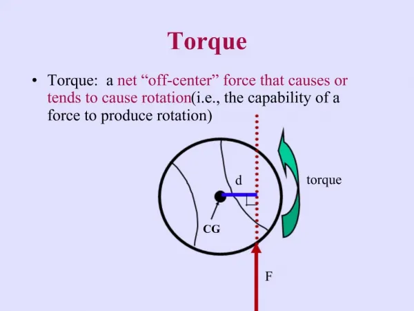
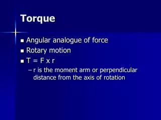
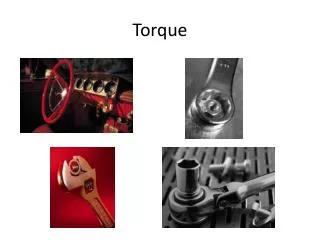
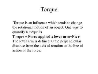
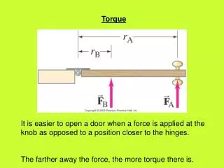
Torque A torque is an action resulting from a force that causes objects to rotate. Torque is not the same thing as force. Torque is created by force, but torque also depends on the point of application and the direction of the force. A door pushed at its handle will easily turn and open, but a door pushed near its hinges will not move as easily.
Torque (cont.) The point or line about which an object turns is its center of rotation. A force applied far from the center of rotation produces a greater torque than a force applied close to the center of rotation. Doorknobs are positioned far from the hinges to provide the greatest amount of torque for a given force.
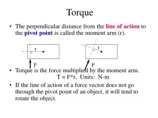
Torque (cont.) Torque is created when the line of action of a force does not pass through the center of rotation. The line of action is an imaginary line that follows the direction of a force and passes though its point of application.
Torque (cont.) To get the maximum torque, the force should be applied in a direction that creates the greatest lever arm. The lever arm is the perpendicular distance between the line of action of the force and the center of rotation
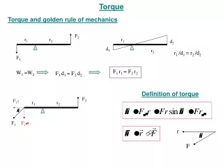
The torque created by force • The torque created by a force is equal to the lever arm length times the magnitude of the force. • Torque is usually represented by the lower case Greek letter “tau,” t. • When calculating torque, if the line of action passes through the center of rotation, the lever arm is zero, and so is the torque, no matter how large a force is applied.
Calculating Torque Lever arm length (m) t = r x F Torque (N.m) Force (N)
Calculating Torque (cont.) • If more than one torque acts on an object, the torques are combined to determine the net torque. • If the torques make an object spin in the same direction, clockwise or counterclockwise, they are added together.
Measurement of applied torque is of fundamental importance in a rotating shaft. • It will ensure that the design of the rotating element is adequate to prevent failure under shear stress. • Torque measurement is necessary to know the power transmitted by the rotating shafts
Measuring the reaction force in cradled shaft bearing. Measuring ‘prony brake’ method. Measurement of induced strain. Optical torque measurement.
the reaction force in cradled shaft bearing cont… The torque transmission through a shaft contains both power Source and absorber power . The torque is measured by cradled either the power source or the Power absorber end of the shaft bearing and then measuring the reaction force(F) and the arm length(L).
2- prony brake method : If the measured force in the spring balance is Fsb. Then the effective force Feff exerted by the rope on the shaft is given by: Feff = mg- Fsb If the radius of the shaft is Rsh and that of the rope is Rro then the effective radius Reff = Rsh+Rro Rsh≡radius of shaft Rro ≡radius of rope
Finally the torque in this method will given by: T= Feff . Reff
Optical torque measurement cont… • Optical techniques for torque measurement have become available recently with the development of laser diodes and fiber-optic light transmission systems.
Optical torque measurement cont… The advantages: • Their small physical size. • The cost of such instruments is relatively low. • The most effective way and more accurate than previous methods. • The optical torque sensor is a non-contact sensor
Optical torque measurement cont… The disadvantages: • It requires slightly more sophisticated processing electronics. • It requires an air gap with a clear optical path.
Measuring the Strain Produced in a Rotating Shaft due to applied Torque This method basically depends on the strain gauges, so let us take a look at what do we mean by a strain gauge??!! Here we GO!!
Measuring the Strain Produced in a Rotating Shaft due to applied Torque (cont’d) • A strain gauge is a small electrical element printed on a non-conductive substrate. • The pattern of the element is arranged so that if the gauge is stretched (or compressed) in one direction (along operating axis of the gauge), the resistance of the element increases (or decreases) in relation to that stretch. • A stretch in which it is perpendicular to the axis of the strain gauge has little effect on the resistance of the element.
Measuring the Strain Produced in a Rotating Shaft due to applied Torque (cont’d) • If a gauge is bonded to the shaft, with its axis aligned with the direction in which the shaft material stretches when a torque is applied, the strain gauge will also stretch and therefore the element will increase in resistance. • If a gauge is bonded to the shaft, with its axis aligned with the direction in which the shaft material compresses when a torque is applied, the strain gauge will also compress and therefore the element will decrease in resistance.
Measuring the Strain Produced in a Rotating Shaft due to applied Torque (cont’d) • In the Torque transducer, strain gauges making up four resistive elements are bonded to the shaft. Two elements are aligned with the direction of Tension (stretch). The remaining two are aligned with the direction of Compression.
Measuring the Strain Produced in a Rotating Shaft due to applied Torque (cont’d) • The four resistive elements are electrically connected in a ‘Wheatstone Bridge’ configuration. • The Wheatstone Bridge configuration is appropriate for measurement of the small resistance changes produced in the strain gauges, as the combination increases and decreases in resistance it produces a change in output voltage.
Measuring the Strain Produced in a Rotating Shaft due to applied Torque (cont’d) Now let’s Go ahead with the Method!!
Measuring the Strain Produced in a Rotating Shaft due to applied Torque (cont’d) • It is the most common method used for torque measurement. • It doesn’t disturb the measured system by introducing friction torque the same way as do the last two methods described. • That’s because it converts torque into an electrical signal. • Electrical signal is preferred over the mechanical signal because of: • It can be transmitted over a long distance. • It can be digitized & displayed.
Measuring the Strain Produced in a Rotating Shaft due to applied Torque (cont’d) • It consists of: • Mechanical System (shaft). • Sensors (strain gauges).
Measuring the Strain Produced in a Rotating Shaft due to applied Torque (cont’d) • The four strain gauges are mounted on two perpendicular 45° helixes. • The strain gauges 1 and 3 are mounted on the right hand helix and these are under elongation. • The strain gauges 2 and 4 are mounted on the left hand helix and these are under compression.
References • Measurement & Instrumentation Principles by Alan.S.Morris. • Measurement , Instrumentation and Sensors Handbook. • www.scribd.com and other internet Resources.
Professor: AlokBarua, Department of Electrical Enginnering, Indian Institute of Technology, (IIT) Kharagpur. Special Thanks To