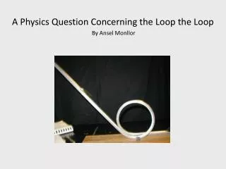
A Physics Question Concerning the Loop the Loop By Ansel Monllor
250 likes | 435 Vues
A Physics Question Concerning the Loop the Loop By Ansel Monllor. Table of Contents. Slide 1 - Title Slide 2 - Glossary Slide 3 - About Me Slide 4 - The Question Slide 5 - Hypothesis Slide 6 - Research Slide 10 - Purpose Slide 11 - Materials Slide 13 – Procedure

A Physics Question Concerning the Loop the Loop By Ansel Monllor
E N D
Presentation Transcript
A Physics Question Concerning the Loop the Loop By Ansel Monllor
Table of Contents • Slide 1 - Title • Slide 2 - Glossary • Slide 3 - About Me • Slide 4 - The Question • Slide 5 - Hypothesis • Slide 6 - Research • Slide 10 - Purpose • Slide 11 - Materials • Slide 13 – Procedure • Slide 20 - Data • Slide 21 - Observations • Slide 22 - Conclusion • Slide 23 - Bibliography • Slide 24 – Glossary of Terms
About me • My name is Ansel Monllor and I am in the seventh grade. I have always been homeschooled so, I have never been to a regular school and I have never participated in any Science Fair or done any major science experiment like this one. • I am new to FLVS and I am currently enrolled in Comprehensive Science, Mathematics, Language Arts and World Cultures. I try to maintain an “A” average. • I am a licensed Amateur Radio Operator and my call sign is KJ4ZRU. I built my very first High Frequency, QRP (Low Power) transceiver. • I recently built my first robot with some help from my dad and I used the Arduino micro-controller to control the actions of my robot. Here is a link to the video: http://www.youtube.com/watch?v=1qHSnT24W3s&list=UU-DB0tD_bDTA1M_Ji3a8d_A&index=2&feature=plpp_video • I also help my dad in his machine shop when I can and I am able to run a metal cutting lathe and a milling machine. • I started teaching myself how to program using Small Basic and I am working my way up to Visual Basic. • I also love science and mathematics and I enjoy dancing with my older sister.
The Question Does a loop the loop in a ride, make a difference on the ride’s total run time?
Hypothesis I hypothesize that, the vertical loop the loop will have no affect on the time it takes a ball to travel the given length of track, from beginning to end, when compared to a straight track or a track with no loop the loop. The ball is still running a given length of track from start to finish. The kinetic energy used going up the loop the loop, is offset by the gravitational force exerted on the ball while exiting the loop the loop.
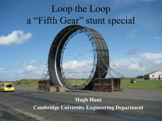
Research The Loop the Loop (Taken from Chaos Toys Web site) You have probably noticed by now that, if the ball is not going fast enough when it enters the loop the loop, the ball will not make it around the entire loop. Let's see if we can figure out exactly what is going on. Set up a simple loop the loop as shown below.
I have marked some heights next to the loop the loop, h being the point where the ball is being released, D being at the top of the loop and 0 being at the bottom. How high does the ball have to be to make it around the loop the loop? In order for the ball to go around the loop the loop, it must have enough speed that the centrifugal force is at least equal to the force of gravity at the top of the loop and because the ball is rolling, using up some of it’s energy, the ball will not make it around the entire loop. It can be shown that if the ball just slides completely and doesn't roll, the minimum height to make it around the loop is h (Height of Ball) = 5D (Height of Loop)/4. If the ball does not slip at all and rolls, then the minimum height is 27D/20. This is slightly higher because some of the energy goes into making the ball roll. Actually, the ball both rolls and slips, so our minimum height should be between the two if there are no other losses of energy. Any movement of the track will take away a little bit of the energy away from the ball, also if the track is not perfectly straight it will take a little bit of energy away from the ball, so the ball will have to be released from a higher point to compensate for that. By measuring how much higher you have to release the ball, you can figure out how much energy is actually being lost.
Here is the math for the loop the loop I found on the Chaos Toys Website: m is the mass of the ball g is the acceleration due to gravity, or 9.8 meters/second squared. h is the height above some reference plane, or ground. mgh is potential energy D is Diameter r is radius kinetic energy is given by (1/2)mv² where m is mass and v is the velocity of the ball. v²/r = centripetal acceleration, and for the ball not to fall out at the top of the loop, this must be equal to g, or 9.8 ms² If the ball does not roll but instead slips, at the top of the loop the kinetic energy must be enough so that the centripetal force equals gravity. aaaaaaaaaaaaaaaaaaaaaaaaaaaaaaaaaaaaaaaaaaaaaaaaaaaaa
Mg(h-D) = (1/2)mv² and v²/r = g and r = D/2 So (g-D) = v²/2g v² = gr = gD/2 Substituting in for v² gives: (h-D) = (gD/2)(1/2g) = D/4 So h = 5D/4 This is the minimum value for h. Now let's include the energy of the rolling ball. If the ball rolls without slipping, the energy due to the rotation is (1/5)mv². If we add this energy to the previous problem Mg(h-D) = (1/2)mv² + (1/5)mv² = (7/10)mv² Again, substituting v² = gD/2 h-D = (7/10)v²/g = (7/10g)(gD/2) = 7D/20 So h = 27D/20. This is the minimum value for h if the ball rolls without slipping.
Purpose The purpose of this experiment is to see if a vertical loop the loop, incorporated into the middle of a straight track, will change the time it takes a steel ball to travel the length of the track, when compared to a track with no loop the loop.
Materials Materials used in this experiment were: Frame and Track 660 cm. of Polyethylene tubing (¼” x .170”, O.D. X I.D.) 660 cm. of 14 gauge galvanized wire 22 pieces of 15 cm. 14 gauge galvanized wire 3 – 2.54 cm. X 5.08 cm. X 243.84 cm. (1” x 2” x 8’) Poplar lumber 1 – 2.54 cm. X 10.16 cm. X 365.76 cm. ( 1” X 4” X 12’)Poplar lumber Wood Glue, Hot Glue and Screws Electronic Timer Arduino Uno Micro-controller Bread Board 1 X 16 X 2 parallel LCD display (compatible with Hitachi HD44780 driver)
1 – 10k ohm potentiometer 1 – 10k ohm resistor 4 - pieces of 1cm. X 5 cm. tin strips cut from a can (to be bent onto tubing for triggers). Jumper wire 1 piece of cushy foam (to be set-up over bottom trigger for positive contact between ball and bottom trigger) Steel Ball 1 – 15.86 mm. (5/8” steel ball, this one weighed 16.31 g.) Power for timer 6v – 9v Battery
Procedure - The Journey Begins One evening my dad and I were talking about rollercoaster's and I wondered if a loop the loop would make a car go faster or slower. We talked about it for some time and remembered that we had just purchased some materials to make a marble run, so why not experiment with what we had, to find out the answer. We purchased some 1” X 2” poplar along with some 1” X 4” X 96” poplar and built an adjustable frame.
BBBBBBBBBBBBBBBBBBBBBBBBBBBBBBBBBBBBBBBBBBBBBBBBBBBBBBBBBBBBBBBBBBBBBBBBBBBBBBBBBBBBBBBBBBBBBBBBBBBBBBBBBBBBBBBBBBBBBBBBBBBBBBBBBBBBBBBBBBBBBBBBBBBBBBBBBBBBBBBBBBBBBBBBBBBBBBBBBBBBBBBBBBBBBBBBBBBBBBBBBBBBBBBBBBBBBBBBBB We carefully marked off every 6 Inches on the tubing with red tape (photo above) and then drilled a hole at the six inch intervals and ran a piece of wire through the holes, in both pieces of tubing, as in the picture above. We then inserted the wired tubing into the frame (picture on the right). Once the basic wooden frame was assembled we got polyethylene tubing ¼” x .170”, O.D. X I.D. and inserted 14 ga. galvanized wire into the tubing in order to be able to shape the tubing to our needs.
The track itself is 282 cm. long from start trigger to end triggerand the loop diameter is 20 cm., located 147 cm. from the starting trigger. The top trigger is located 43 cm. high from the top of the base frame. 147 cm.
We need to accurately record the time. In order to time the runs accurately, we needed to devise an electrical stopwatch where a trigger at the top of the track would start the stopwatch and a trigger at the end of the track would stop the stopwatch. We used an Arduino micro-controller and a Stopwatch sketch written specifically for Arduino users. A sketch is the written program used to tell the micro-controller what to do and how to do it. We had to make some adjustments to the original wiring layout. In the diagram on the left, the small brown momentary on/off switch on the bottom board, was replaced with one pair of wires connected to the trigger at the top of the track and a second pair of wires, connected in series to the first pair of wires, run to the second trigger at the end of the track. The original Stopwatch Sketch was also altered to be able to read inputs from two separate triggers instead of just one switch.
We enlisted the help of Mr. Don Jeerings, retired electrical engineer and inventor, on this project. Don originally proposed that we use photo-resister switches, which would toggle on and off when a small LED’s light beam would be broken by the passing ball over the photo resistor.
After 2 weeks of program hacking and different wiring strategies, we could not get both triggers to operate correctly, so we decided that we would use metal, mechanical switches instead and we placed a small piece of sponge material over the bottom trigger in order for the ball to have positive contact with that trigger. We included a starting gate to omit any unintended human variable there might occur when letting go of the ball. Top trigger and starting gate Bottom trigger and foam
Running the Experiment We connected the battery to the Arduino based stopwatch. We placed the steel ball behind the starting gate. We lifted the gate, which started the stopwatch. The steel ball ran the course to the end of the track, which stopped the stopwatch. We executed 10 experimental runs with the loop the loop in the track, then we straightened out the track and executed 10 runs without the loop the loop.
Data Here are the results done in an excel worksheet.
Observations and things I Learned • My observations and the recorded stopwatch times, clearly show that my hypothesis was not correct. In as much as the ball travelled the same amount of track on every run, the times do show that a loop the loop placed in the middle of the track, decreases the speed of the steel ball, because of the introduction of forces not there, when compared to a track without a loop the loop. • I also learned through doing this experiment that a straight track run will always use less energy than a track run with twists and turns in it. • I learned about how important it is to keep variables in an experiment to a minimum. • My greatest observations came while doing the research for this presentation. My observations were that, science and mathematics go hand in hand with each other and that as I get the answer to one question, at least one other question comes up. I would have never thought that so many things happened as a ball went around a loop the loop.
Conclusion • In conclusion an object will always run faster on a straight track rather than one with loop the loops because there are less forces absorbing some of the balls energy.
Bibliography • http://www.chaostoy.com/ • http://arduino.cc/ • http://arduinoprojects101.com/arduino-stopwatch/ • http://www.nuffieldfoundation.org/practical-physics/experimental-test-f-mv%C2%B2r • http://en.wikipedia.org/wiki/Main_Page
Glossary of Terms M = mass R = radius v = speed of the object g = the acceleration of free fall a = v²/R is centripetal acceleration mv²/R is the predicted centripetal force for a given orbit Centrifugal force - An outward pressure exhibited by an object rotating around a central point. Centripetal force - a force which keeps a body moving with a uniform speed along a circular path and is directed along the radius towards the centre. Potential Energy - is energy stored in an object. In this instance, I am referring to the stored energy created by the gravitational force which is at work here. When you move an object upward it gains potential energy due to gravity. Kinetic Energy – It is the energy of motion. All moving things have kinetic energy and the faster they are moving, the more energy they have.
Glossary of Terms Centripetal acceleration - is the rate of change of tangential velocity. Tangential velocity - is the instantaneous linear velocity of a body moving in a circular path.