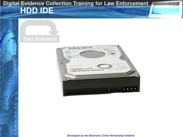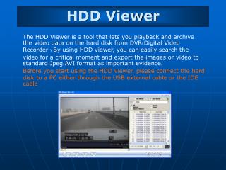
HDD Failures and Handling
1.47k likes | 1.9k Vues
HDD Failures and Handling. School of Mechanical Engineering Institute of Engineering Suranaree University of Technology. Measurement and Test requirements. Disc Balance Acoustic Leak test NRRO & RRO Track registration. Measurement and Test requirements.

HDD Failures and Handling
E N D
Presentation Transcript
HDD Failures and Handling School of Mechanical Engineering Institute of Engineering Suranaree University of Technology
Measurement and Test requirements • Disc Balance • Acoustic • Leak test • NRRO & RRO • Track registration
Measurement and Test requirements ฮาร์ดดิสก์ถูกออกแบบให้ทำงานตามข้อกำหนดทางเทคนิคต่างๆ เช่น • shock,vibration,temperature,humidity,altitude และ magnetic field • ถูกป้องกันจาก ESD • Breathing hole บน top cover จะต้องไม่ถูกสิ่งของหรือวัสดุอื่นมาปิดไว้ • ไม่มีแรงภายนอกมากระทำ หรือกดต่อฮาร์ดดิสก์ • ขนาดของกระแสและกำลังไฟฟ้าที่ป้อนให้กับฮาร์ดดิสก์อยู่ในพิกัดที่เหมาะสม
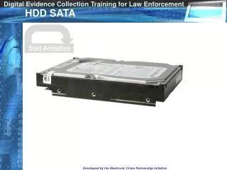
Measurement and Test requirements ฮาร์ดดิสก์ถูกออกแบบให้ทำงานตามข้อกำหนดทางเทคนิคต่างๆ(ต่อ) • ฮาร์ดดิสก์ถูกต่อลงดินผ่านสกรูที่ใช้ยึดฮาร์ดดิสก์เข้ากับสิ่งที่ถูกติดตั้ง • สกรูที่ใช้ถูกขันยึดด้วยแรงบิดที่กำหนด ความลึกที่กำหนด • Interface เหมาะสม เช่น SATA • Power-off sequence ของฮาร์ดดิสก์ถูกกำหนดแล้วตาม “Required power-off sequence.”
Measurement and Test requirements • Disc Balance • Acoustic • Leak test • NRRO & RRO • Track registration
Disk Balance • A disk drive recording device comprises at least two platters for storing magnetic recording data and a spindle motor rotating at high speed for mounting the platters.
Disk Balance • The disk drive is assembled by using pushing devices to push the platters toward the center of the spindle motor in respective directions to bring a portion of an inside circumference of a concentric center hole of each of the platters in contact with an outer circumference of the spindle motor so that the center of gravity of each platter coincides with a center axis of the spindle motor.
Disk Balance • Method for balancing a rotating assembly using eccentric rings (United States Patent 6947253)
Measurement and Test requirements • Disc Balance • Acoustic • Leak test • NRRO & RRO • Track registration
Acoustic Sound power level • Measurements are to be taken in accordance withISO 7779. • The mean of the sample of 40drives is to be lessthan the typical value. • Each drive is to be less than the maximum value.
Acoustic • The sound power in dB converted from Watts as follows:Ten times the common logarithm of the ratio of the acoustic power to the reference sound power, 10-12 W or 1 pW. • The symbol is LW
Acoustic • The criteria of A-weighted sound power level aredescribed below.
Acoustic • The background power levels are to be recorded. • Sound power tests are to be conducted with the drivesupported by spacers so that the lower surface of the drivebe located25±3mm above from the chamber floor. Nosound absorbing material shall be used.
Acoustic The acoustical characteristics of the disk drive aremeasured under the following conditions. • Idle mode - Power on,disks spinning,track following,unitready to receive and respond to control line commands. • Operating mode - Continuous random cylinder selectionand seek operation of actuator with a dwell time at eachcylinder.
Measurement and Test requirements • Disc Balance • Acoustic • Leak test • NRRO & RRO • Track registration
Leak Test • It is air leak test when air pressure is applied into the HDD cavity. • It indicate HDD seal performance.
Measurement and Test requirements • Disc Balance • Acoustic • Leak test • NRRO & RRO • Track registration
NRRO & RRO • Non-repeatable Run-out (NRRO) is one of the main sources of Track Mis-Registration (TMR) which prevents high track density.
NRRO & RRO • It is reported that NRRO is mainly generated by the defect frequencies of ball bearing. • Minimizing NRRO,lowering acoustical noise,andimproving reliability. • There is an upper limit at which the Ball Bearingdesign can no longer overcome the NRROproblem at the higher areal densities. • Currently with Ball Bearings,NRRO has settled inthe 0.1micro-inch range.
NRRO & RRO • Fluid Dynamic Bearing (FDB) motors generates less NRRO due to the higher viscosityof lubrication oil between the sleeve and stator.
NRRO & RRO FDB design • higherdamping • reduced frequency resonance • better non-operational shock resistance • greater speed control • improved acoustics.
NRRO & RRO Error Types: NRRO (Non-Repeatable Run-Out) • External shock and vibration (other spindles) • Spindle bearing runout (periodic but notsynchronous) • Air turbulence: disk vibration/flutter,actuatorwindage • Actuator pivot and flex cable bias (nonlinear)
NRRO & RRO Error Types: RRO (Repeatable Run-Out) • Synchronized to spindle rotation • Disk slip,thermal motion,drive induced vibration,STW NRRO • Compensation techniques (include peak filter andfeed forward)
Measurement and Test requirements • Disc Balance • Acoustic • Leak test • NRRO & RRO • Track registration
Track registration • Disk Transfer Rate: The test defines the linear reading speed inthousand bytes/sec. In the end,the test gives twonumerical values - speed in the beginning and inthe end of the disc.
Track registration • Disk Access Time: The test defines an access time in ms. The final value is equal to the sum of average latency and average seek time. • Disk CPU Utilization: The test shows the CPU utilization in percents in thecourse of data exchange with a disc.
Failures • Failures • Media Failures • Head Failures • Head-Media Spacing / Fly Height • PCBA Failures • Mechanical Failures • Thermal Asperity (TA) • Off Track Read/Write
Media Failure • the platters and the magnetic media, • servo operation and the like. • read or write errors, • poor handling, • scratches on the media surface, • errors in low-level formatting, etc.
Head and Head Assembly Failures • improper flying height, • head contamination, • defects in head manufacture, • bad wiring between the heads and the logic board
Head-Media Spacing / Fly Height There are many ways that hard disk can fail • The most famous way is “Head crash” • Head crashes is are the "airline disasters" of the hard disk world but actually responsible for a small percentage of total drive problems
Head crashes on HDD Above: A severe headcrash on a SCSI hard disk
Head crashes on HDD • Cause: • dust or contamination • sudden jolt or shock. • Recovery Possibilities: • Most of head crash are completely unrecoverable • some head crashes are mild and most of the data can be recovered.
Logic Board or Firmware Failures related to the drive's integrated logic board, its chips and other components, and the software routines (firmware) that runs it.
Mechanical Failures • the spindle motor or bearings, • motor burnout, • "stuck" bearings, • excessive heat, • excessive noise and vibration. • Actuator problems
Thermal asperity(TA) Definition: A TA is a read signal spike caused by sensor temperature rise due to contact with disk asperities or contaminant particles. • Cause: TA’s may cause GMR or MR heads to temporarily lose their reading capability, and may potentially damage the transducer.
Track average amplitude (TAA) Definition: the average peak-to-peak value of the data over a specified range of sectors Depends on • the density of the drive’s platter • the sensitivity of theread-channel. If the TAA is too high, the magnetic flux from the platter willcause the MR head to saturate, which distorts thewaveform that the head sends to the preamp. If the TAA is too low, causing random bit errors.
Clean room's critical control • ESD control • Contamination control
Electrostatic Discharge (ESD) • Electrostatic discharge (ESD) is the sudden and momentary electric current that flows between two objects at different electrical potentials (such as ground). The term is usually used in the electronics and other industries to describe momentary unwanted currents that may cause damage to electronic equipment.
Type of ESD Damage • Upset Failure • Catastrophic Failure
Upset Failure Upset failures occur when an electrostatic discharge has caused a current flow that is not significant enough to cause total failure, but in use may intermittently result in gate leakage causing software malfunction or incorrect storage of information.
Catastrophic Failure • Direct catastrophic failures occur when a component is damaged to the point where it no longer functions correctly. • Latent catastrophic failures occur when ESD weakens a component to the point where it still functions correctly during testing, but subsequent minor electrical overstresses or power surges during normal operation of the equipment cause the component to fail.
ESD Test Models • Human-Body Model (HBM) • Machine Model (MM) • Charged-Device Model(CDM)
R=1 MΩ R=1.5 kΩ C= 100 pF MR Human-Body Model (HBM) The HBM was developed to simulate the action of a human body discharging accumulated static charge through a device to ground, and employs a series RC network consisting of a 100-pF capacitor and a 1500-Ω resistor.
RL=1 Ω R=1 MΩ C= 200 pF MR Machine Model (MM) The MM simulates a machine discharging accumulated static charge through a device to ground. It comprises a series RC network of a 200-pF capacitor, and nominal series resistance of less than 1 ohm. The output waveform usually is described in terms of peak current and oscillating frequency for a given discharge voltage.
Charged-Device Model(CDM) The CDM simulates charging/discharging events that occur in production equipment and processes. Potential for CDM ESD events occur when there is metal-to-metal contact in manufacturing.
Controlling ESD • Dissipate and Grounding • Isolation • Prevention
Dissipate and Grounding Grounding is a means of draining the static charges present on your body, by use of a personal grounding device or a wrist strap. • Human Suit • Machine • Tools • Working Area
Isolation Isolation can also be accomplished by keeping charge generating materials away from working area • plastic bags • cellophane tape • paper work • common untreated plastic materials • styrofoam cups
Isolation • during storage and transportation • packing of components and assemblies to protect static charges cannot penetrate • containers made of conductive materials or have a conductive layer.