
Map Projections & Coordinate Systems
E N D
Presentation Transcript
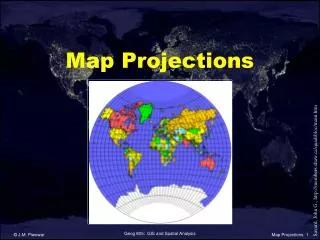
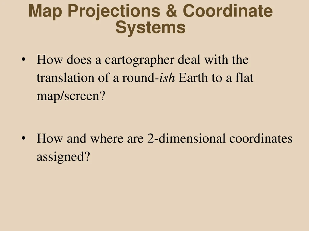
Map Projections & Coordinate Systems • How does a cartographer deal with the translation of a round-ish Earth to a flat map/screen? • How and where are 2-dimensional coordinates assigned?
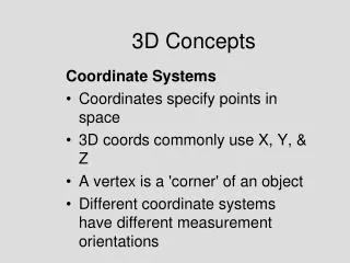
The Earth’s shape is not truly spherical: There is a slight bulging at the equator and flattening at the poles due to the centrifugal force generated by the Earth’s rotation The closest mathematical approximation of Earth’s shape is an oblate spheroid or an ellipsoid Better is a Geoid (not a mathematical model but a model of mean sea level based on survey measurements taken across the planet) Not a problem for smallscale maps of the Earth - a sphere is sufficient In order to be accurate, larger scale maps must use an ellipsoid (or geoid) as a base (earth model) Datums are built upon an ellipsoid (or a geoid) in conjunction with local/regional survey control points (Ex: North American Datum 1927 (NAD27); Kertau 1948 ) Turns out Columbus was wrong… Datums - Spheroids - Ellipsoids - Geoids… An example of an ellipsoid
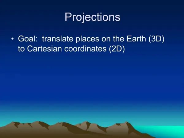
Map Projections • Methods for flattening (unrolling) a roundish earth onto a flat surface • Based on a Datum (which is based on an ellipsoid) • Ellipsoid (earth model) changes, the datum changes – (Clarke 1866 = NAD 1927) v. (GRS 1980 = NAD 1983) • The shapes of the earth land features are ‘projected’ onto a flat surface – as if a light were aimed at the planet casting a shadow
Datum Shift 4790 1000m 700m 275m 4789 Datum corner NAD27 4788 543 541 542
Datum Shift 4790 1000m 600m 350m 4789 Datum corner NAD83 4788 543 541 542
Common Developable Surfaces Basic Types of Map Projection Plane Cone Cylinder
Common Developable Surfaces Basic Types of Map Projection Plane Cone Cylinder
Map Projections - Cylindrical Tend to be Conformal Globe is projected onto a cylinder tangent at equator (typically) Low distortion at equator Higher distortion approaching poles A good choice for use in equatorial and tropical regions, e.g., Ecuador, Kenya, Malaysia
Mercator Projection Invented by Gerhardus Mercator - Flemish cartographer - in 1569 A special purpose projection intended as a navigational tool A straight line between two points gives a navigator a constant compass bearing to the destination - not necessarily the fastest route A cylindrical projection
Map Projections - Conic Tend to be Equal Area Surface of globe projected onto cone tangent at standard parallel Distorts N & S of standard parallel(s) Normally shows just one semi-hemisphere in middle latitudes
Map Projections – Planar or Polar Planar or Polar Projection -- Conformal Conformal Surface of globe is projected onto a plane tangent at only one point (frequently N or S pole) Usually only one hemisphere shown (often centered on N or S pole) Works well to highlight an area Sometimes used by airports Shows true bearing and distance to other points from center/point of tangency
Map Projections – Distortion Conformal vs. Equal-area (The Great Debate) Preserve true shapes Preserve angles Exaggerate areas Graticules perpendicular Show true size (area) Distorts shapes, angles and/or scale (squish/stretch shapes) Graticules not perpendicular OR
Distortion: direction and distance Conformal vs. Equal-area Northwest North Northeast
Map Projections - families & examples Elliptical/Pseudocylindrical (football) Projection Tend to be equivalent (equal-area) Not bad for world maps Mollweide projection
Map Projections - families & examples Goode’s Homosoline Interrupted Elliptical Projection • Equivalent/equal area • Good for climate, soils, landcover - latitude and area comparisons • Mild distortion of shapes • Interrupts areas - oceans, Greenland, Antarctica - sometimes reversed
Map Projections - families & examples Waterman Polyhedron “Butterfly” Projection • Good approximation of continents’: • size • shape • position
Johann Heinrich Lambert (1728-77) Map Projections Two to Remember 1. Conformal Conic A conic with two standard parallels (used for some State Plane systems) 2. Transverse Mercator A rotated cylindrical with the tangent circle N-S instead of along the Equator (used for UTM & some State Plane systems) Lambert invented two of the most important and popular projections in use today Lambert Conformal Conic Transverse Mercator
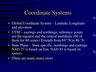
Map ProjectionsCoordinate Systems For a spatial database to be useful, all parts must be registered to a common coordinate system. Coordinate Systems (other than latitude-longitude) use a particular Projection, as well as a particular Datum (which is based upon a particular Ellipsoid or Geoid)…
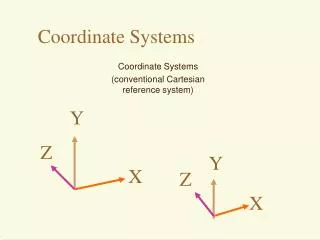
Coordinate Systems Three to Remember 1. State Plane 2. Universal Transverse Mercator (UTM) 3. Latitude-Longitude (a spherical coordinate system)
False origin for WA. N. zone Coordinate Systems: State Plane Coordinate System • Created in the 1930’s, zones follow state/county boundaries • Each zone uses a projection: Lambert’s Conformal Conic (E-W zones) Transverse Mercator (N-S zones) • Each zone has a centrally located origin, a central meridian and a false origin established to the W and S • Don’t have to deal with negative numbers • Uses planar coordinates (instead of Lat./Long. spherical coordinates) • Square grid with constant scale - distortion over small areas is minimal • USA only Zones of the SPCS for the contiguous US
Coordinate Systems: Universal Transverse Mercator • Convenience of a plane rectangular grid on a global level • Popular in scientific research • A section from a transverse Mercator projection is used to develop separate grids for each of 60 zones • Low distortion along the tangent central meridian, increasing E & W • Works great for large scale data sets and satellite image rectification though some areas cross zones (WA, TN, etc.) Beginning at 180o, Transverse Mercator projections are obtained every 6 degrees of longitude along a central meridian
Coordinate Systems: Universal Transverse Mercator • 60 N-S zones each spanning 6o of longitude (0.5o overlap each side) from 84o N - 80o S • In polar regions the Universal Polar Stereographic grid system (UPS) is used • Each zone has an origin, central meridian, and false origin, just as with SPCC • Coordinates read similar to SPCC but in meters: UTM zones (10-19 North) covering the lower 48 states
Coordinate Systems: Lat./Long. (Geographic Coordinates) • Works for a sphere or spheroid • Lines of latitude begin at the equator and increase N and S toward the poles from 0o to 90o • Degrees of Latitude are constant • Lines of Longitude begin at some great circle (prime meridian) passing through some arbitrary point • 1o of Longitude = 1o of Latitude only at the Equator. Degrees of Longitude get smaller (converge) towards poles • Technically, Unprojected (a spherical coordinate system) NOT Projected “Geographic Coordinate System”
So why does this matter? GIS programs must know what projection was used for data creation and where the Coordinate System’s point of origin is… Map data or satellite images in different projections, coordinate systems, or referenced to different datums may not overlay properly…
So why does this matter? Things work best in ArcMap if the Data and the Data Frame use the same coordinate system, projection and datum… ArcMap can project data (using one coordinate system) to another, different coordinate system (e.g., that of the Data Frame) if the coordinate systems of the data and the data frame are properly defined If the Data and Data Frame use different Datums, a Datum Transformation must be chosen
Summary A round-ish earth must be ‘projected’ onto a developable surface in order to make a flat map. Common developable surfaces are: • Plane • Cylinder • Cone Two common Projections used in the USA are: • Lambert’s Conformal Conic • Transverse Mercator (Cylindrical, a variant of the classic Mercator projection) Coordinate Systems assign a unit of measurement and a point of origin. These require a projection as well as a datum (earth model). Three common Coordinate Systems used in the USA are: • Latitude-Longitude (which is technically unprojected (or ‘geographic’), but still requires a datum, and uses speherical coordinates as opposed to planar coordinates) • UTM (Universal Transverse Mercator) • State Plane