MULTIPLE ACCESS TECHNIQUES AND NETWORK ASPECTS
MULTIPLE ACCESS TECHNIQUES AND NETWORK ASPECTS. Multiple Access . Aim is to develop Efficient Techniques that Maximize System Capacity thru Dynamic Resource Allocation and Spectrum Reuse. How do we share one transponder between several earth stations?. NEED TO OPTIMIZE

MULTIPLE ACCESS TECHNIQUES AND NETWORK ASPECTS
E N D
Presentation Transcript
Multiple Access • Aim is to develop Efficient Techniques that Maximize System Capacity thru Dynamic Resource Allocation and Spectrum Reuse
How do we share one transponder between several earth stations? • NEED TO OPTIMIZE • Satellite capacity (revenue issue) • Spectrum utilization (coordination issue) • Interconnectivity (multiple coverage issue) • Flexibility (demand fluctuation issue) • Adaptability (traffic mix issue) • User acceptance (market share issue) • Satellite power • Cost
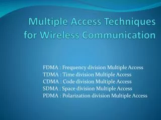
How do we separate users? • Label the signal in a unique way at the transmitter • UNIQUE FREQUENCY SLOT FDMA • UNIQUE TIME SLOT TDMA • UNIQUE CODE CDMA • Recognize the unique feature of each signal at the receiver
Channel Allocation Pre-Assigned Channel Allocation A given number of available voice-band channels from each earth station are assigned to a dedicated destination….Some-times wastage of Precious BW Resource Demand-Assigned Channel Allocation Resources allocation is on need basis, versatile and efficient usages of Radio Spectrum, but a Complex Mechanism is required at all Earth Stations/Users
CHANNEL RECOGNITION? • Multiple access methods
Difference between multiplexing & multiple Access • Multiplexing is sharing of resources on links inside the network • Multiple Access is sharing of resources on the access part of the network.
Difference between multiplexing & multiple Access MULTIPLEXING (dial up internet) Multiple Access (satellite internet)
Two way communication Inbound or forward link The communication link from the subscriber to the service provider via satellite. Outbound or reverse link The communication link from the service provider to the subscriber via satellite. ----- inbound link Out bound link
Frequency division multiple access(FDMA) • All users transmit at the same time but at different frequencies • E.g. Satellite phone • Nearly every terrestrial or satellite radio communications system employs some form of FDMA to divide up the available spectrum. The areas where it has the strongest hold are in • single channel per carrier (SCPC), • intermediate data rate (IDR) links, • voice telephone systems, • VSAT data networks, and some • video networking schemes.
FDMA • Any of these networks can operate alongside other networks within the same transponder. • Users need only acquire the amount of bandwidth and power that they require to provide the needed connectivity and throughput. • Also, equipment operation is simplified since no coordination is needed other than assuring that each Earth station remains on its assigned frequency and that power levels are properly regulated. • However, inter-modulation distortion (IMD) present with multiple carriers in the same amplifier must be assessed and managed as well.
FDMA • The satellite operator divides up the power and bandwidth of the transponder and sells off the capacity in attractively priced segments. • Users pay for only the amount that they need. If the requirements increase, additional FDMA channels can be purchased. • The IMD that FDMA produces within a transponder must be accounted for in the link budget; otherwise, service quality and capacity will degrade rapidly as users attempt to compensate by increasing uplink power further. • The big advantage, however, is that each Earth station has its own independent frequency on which to operate.
INTERMODULATION • It is the unwanted amplitude modulation of signals containing two or more different frequencies in a system with nonlinearities. • The intermodulation between each frequency component will form additional signals at frequencies that are often at sum and difference frequencies of the original frequencies.
Example • Suppose 3 carriers are carrying three different signals in FDMA mode & pass through HPA of transponder. • One carrier is at 1 MHz, second at 2 MHz & third at 3 MHz . • Due to non linear properties of HPA the 1 & 2 MHz frequencies will produce two Intermodulation products i.e. 2-1 = 1 MHz & 2+1 = 3 MHz . • As there are valid signals already present at 1 & 3 MHz so the Intermodulation signals will interfere with them & produce cross talk. Solution • The carrier power of each signal in FDMA must be reduced before passing through HPA. This is called back off.
Time Division Multiple Access (TDMA) • All users transmit at the same frequency but at different time • TDMA is a truly digital technology, requiring that all information be converted into bit streams or data packets before transmission to the satellite. • So it is resistant to noise & due to large BW available high data rates are possible. • E.g. VSAT inbound link.
TDMA • Develop a burst time plan from user capacity requests • Large system burst time plans can be complicated and difficult to change • Length of burst bandwidth allocated
TDMA Concept • Each earth station transmits in sequence • Transmission bursts from many earth stations arrive at the satellite in an orderly fashion and in the correct order.
TDMA FRAME Pre-amble in each traffic burst provides synchronization, signaling information (e/s tx, e/s rx, etc.), and data “Pre-amble”
TDMA • Timing obtained by • organizing TDMA transmission into frames • each e/s transmits once per frame such that its burst begins to leave the satellite at a specified time interval before (or after) the start of a reference burst • Minimum frame length is 125 s • 125 s 1 voice channel sampled at 8 kHz
Reference burst(s) and pre-amble bits are system overhead and earn no revenue • Traffic bits earn the revenue • Need to minimize system overhead • Complicated system trade-off with number of voice (or data) channels, transmission bit rate, number of bursts, etc.
TDMA –trade off Number of bursts in a frame Transmission bit rate Number of voice channels Frame period For INTELSATR = 120 Mbit/s and TF = 2 ms Bit rate for one voice channel No allowance for guard times
TDMA – MAIN DISADVANTAGE • Delay time to GEO satellite is 120 ms • TDMA Frame length is 125 s to 2 ms • There could be almost 1000 frames on the path to the satellite at any instant in time • Timing is therefore CRUCIAL in a TDMA system
LONG TDMA FRAMES • To reduce overhead, use longer frames • 125 s frame: 1 Word/Frame • 500 s frame: 4 Words/Frame • 2000 s frame: 16 Words/Frame 2000 s = 2 ms = INTELSAT TDMA standard NOTE: 1 Word is an 8-bit sample of digitized speech, a “terrestrial channel”, at 64 kbit/s 8 kHz × 8 bits = 64 kbit/s
Problem • Transponder bandwidth = 36 MHz • Bit rate (QPSK) 60 Mbit/s = 60 bits/s • Four stations share transponder in TDMA using 125 s frames • Pre-amble = 240 bits • Guard time = 1.6 s • Assuming no reference burst we have
#1 #2 #3 #4 FRAME= 125 s Guard time 96 bits = 1.6 s First thing to do: draw theTiming Recovery Diagramto get a picture of the way the frame is put together Traffic: N bitslet it = T s Pre-amble 240 bits= 4 s @ 60 bits/ s
Problem • WITH THE TDMA EXAMPLE • (a) What is the transponder capacity in terms of 64 kbit/s speech channels? • (b) How many channels can each earth station transmit?
Solution • (a) There are four earth stations transmitting within the 125 s frame, so we have • 125 s frame gives125 = (44 s) + (41.6 s) + (4T s) Four earth stations, 4 s pre-amble, 1.6 s guard time, T s traffic bits This gives T = (125 - 16 - 6.4)/4 = 25.65 s60 Mbit/s 60 bits/s, thus 25.65 s = 1539 bitsHence channels/earth station = 1539/8 = 192(.375) 8 bits/word for a voice channel
Solution • (a) What is the transponder capacity in terms of 64 kbit/s speech channels?Answer: 768 (64 kbit/s) voice channels • (b) How many channels can each earth station transmit?Answer: 192 (64 kbit/s) voice channels
TDMA summary • ADVANTAGES • No intermodulation products (if the full transponder is occupied) • Saturated transponder operation possible • Good for data • With a flexible Burst Time Plan it will optimize capacity per connection
TDMA summary • DISADVANTAGES • Complex • High burst rate • Must stay in synchronization
Code division multiple access(CDMA) • All users transmit at the same frequency & at the same time but using different code. • E.g. GPS navigation system.
CDMA • Share time and frequency • Separation of signals is through the use of unique codes • Each user is assigned a code • Station 1 code 1 • Station 2 code 2 • Receiver searches for codes • Code rate >> data rate
CDMA • System operator - or individual pairs of users - assign unique spreading or hopping codes to each duplex link • CDMA is a solution for severe interference environments, usually at a capacity loss compared with TDMA and FDMA • All users share the same time and frequency • Signals are separated by using a unique code • Codes must be “orthogonal” so that UserA does not respond to a code intended for User B • Codes are usually very long : PN sequence, Gold, or Kasami codes
CDMA • CDMA, also called spread spectrum communication, differs from FDMA and TDMA because it allows users to literally transmit on top of each other. • This feature has allowed CDMA to gain attention in commercial satellite communication. • It was originally developed for use in military satellite communication where its inherent anti-jam and security features are highly desirable. • CDMA was adopted in cellular mobile telephone as an interference-tolerant communication technology that increases capacity above analog systems.
CDMA • It has not been proven that CDMA is universally superior as this depends on the specific requirements. • For example, an effective CDMA system requires contiguous bandwidth equal to at least the spread bandwidth. • Two forms of CDMA are applied in practice: (1) direct sequence spread spectrum (DSSS) and (2) frequency hopping spread spectrum (FHSS). • FHSS has been used by the OmniTracs and Eutel-Tracs mobile messaging systems for more than 10 years now, and only recently has it been applied in the consumer’s commercial world in the form of the Bluetooth wireless LAN standard. • However, most CDMA applications over commercial satellites employ DSSS (as do the cellular networks developed by Qualcomm).
DIRECT SEQUENCE CDMA • Multiply the information stream (the data) by a high speed PN code • Use two codes: one for a “1” and one for a “0” • 1 data bit many “Chips”e.g. 2.4 kbit/s 1 Mbit/s The Chip Rate is essentially the code rate from the PN sequence generator The “Spreading factor” is 400, can think of this as coding gain
Summary of DSSS or FHSS • Simplified multiple access: no requirement for coordination among users; • Selective addressing capability if each station has a unique chip code sequence—provides authentication: alternatively, a common code may still perform the CDMA function adequately since the probability of stations happening to be in synch is approximately 1/n; • Relative security from eavesdroppers: the low spread power and relatively fast direct sequence modulation by the pseudorandom code make detection difficult; • Interference rejection: the spread-spectrum receiver treats the other DSSS signals as thermal noise and suppresses narrowband interference.
CDMA • A typical CDMA receiver must carry out the following functions in order to acquire the signal, maintain synchronization, and reliably recover the data: • Synchronization with the incoming code through the technique of correlation detection; • De-spreading of the carrier; • Tracking the spreading signal to maintain synchronization; • Demodulation of the basic data stream; • Timing and bit detection; • Forward error correction to reduce the effective error rate;
CDMA • The first three functions are needed to extract the signal from the clutter of noise and other signals. • The processes of demodulation, bit timing and detection, and FEC are standard for a digital receiver, regardless of the multiple access method.
CDMA application • MILITARY • Anti-Jam (AJ) • Low Probability of Intercept (LPI) • COMMERCIAL • VSATs (due to wide beams) • GPS • Microwave Cellular Systems
Multiple Access Summary • The bottom line in multiple access is that there is no single system that provides a universal answer. • FDMA, TDMA, and CDMA will each continue to have a place in building the applications of the future. • They can all be applied to digital communications and satellite links. • When a specific application is considered, it is recommended to perform the comparison to make the most intelligent selection.