Download
1 / 35
350 likes | 493 Vues
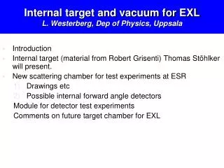
Internal target and vacuum for EXL L. Westerberg, Dep of Physics, Uppsala. Introduction Internal target (material from Robert Grisenti) Thomas Stöhlker will present. New scattering chamber for test experiments at ESR Drawings etc Possible internal forward angle detectors

E N D
Internal target and vacuum for EXLL. Westerberg, Dep of Physics, Uppsala • Introduction • Internal target (material from Robert Grisenti) Thomas Stöhlker will present. • New scattering chamber for test experiments at ESR • Drawings etc • Possible internal forward angle detectors Module for detector test experiments Comments on future target chamber for EXL
Development of Cryogenic Liquid Microjet Sources: Proposal for a High-Luminosity Low-Z Internal Target for the NESR Robert E. Grisenti1,2 1Institute for Nuclear Physics, J. W. Goethe-University Frankfurt am Main 2GSI, Darmstadt
Motivation d0, P0, T0 • By employing the intense beams of highly charged ions stored at the NESR novel atomic structure investigations and QED tests will be possible in collision experiments with low-Z internal targets • The design and development of an internal target is a scientifically important aspect of SPARC at FAIR Current internal-target station at ESR
Low-Z Internal Target at the NESR • Future experiments at the NESR set severe constraints on the main internal target features • Large target density, ideally adjustable in t = nx ~ 1013–1015 cm-2, for all low-Z (H2, D2, He) targets • Small lateral spread at the interaction region, ideally x ~ 1 mm • Gas jet targets (nozzle diameter d0 ~ 100 m) at T0 > 77 K provide small t (~ 1013 cm-2 for H2 and ~ 1011 cm-2 for He) and large x (> 5mm) By expanding the liquid into vacuum at much lower temperatures higher t and smaller x can be achieved
Low-Z Liquid Vacuum Expansion is not Straightforward • The use of sub-10 m diameter nozzles is mandatory in order to • not deteriorate the in-ring vacuum conditions • avoid freezing of liquid hydrogen at the nozzle exit (the H2 nucleation rate scales as ~d03) • Microscale liquid jet operation requires • scrupulous cleaning at all stages of beam preparation • sub-micrometer filtering • the use of ultrahigh-purity gases
Sub-10 m Liquid He Beams: Experimental The cryostat can rotate around its axis d0 = 2 m T0 = 1.3-4.2 K
The Nozzle Unit Cryostat cold head Nozzle plate Filter (0.5 m) Sealing screw 35 mm
Sub-10 m Liquid He Beams: Results P0 = 3 bar T0 = 4 K Grisenti and Toennies, PRL 90, 234501 (2003)
Sub-10 m Liquid He Beams: Results P0 = 3 bar T0 = 4 K Liquid He microjet generated in Frankfurt at T0 = 3.8 K, source cooled by means of a continuous flow cryostat
Liquid He Beam Fragmentation Modes Droplet diameter [Å] Number of atoms per droplet
What does it mean for the target density? x d0 n0 R • Mass conservation implies <t> = nx ≈ n0x d0 / (R • With n0 ≈ 2·1022 cm-3, R = 2 m, x= 1 mm,and ≈ 1–10mrad • <t> ≈ 2·1013 – 2·1015 cm-2
Frankfurt Apparatus (H2, D2, He Beams) Expansion chamber with pressure ~10-5mbar with a pumping speed of 2000 l/s (three orders of magnitude smaller than at ESR!) Filtering system (0.5 m pores filter immersed in liquid nitrogen)
Frankfurt Apparatus (H2, D2, He Beams) Continuous flow cryostat mounted on a x-y-z adjusting platform (could be stored in remote mode by high-precision step motors). 100 l LHe allow for about 150 hours continuous operation at 4 K 400 mm
High-Resolution Shadow Imaging • Optics: 2Mx2M CCD camera and 12x zoom objective (providing up to 1 mm spatial resolution) • Back-side illumination: double pulse laser operating at 532 nm, pulse width <20 ns and repetition rate up to 10 Hz, coupled to a diffuser
Rayleigh Breakup of Liquid H2 in Vacuum P0 = 4 bar d0 = 2 m VACUUM! T0 = 16 K Droplet diameter ≈ 4m
Beam Lifetimes vs. Target Density • Charge-exchange processes (e.g., REC) limit the maximum internal-target thickness • Estimation of beam lifetimes was made based on the huge amount of charge-exchange cross-section data collected at the ESR — 1014 cm-2 — 1015 cm-2 — no target 740 MeV/u
Summary and Outlook • A very compact, sub-10 m cryogenic liquid beam source is proposed as low-Z (H2, D2, He) internal target providing large target densities(up to ~ 1015 cm-2) and small lateral spreads (~ 1 mm) • The proposed source is also well suited for heavier elements (Ne, Ar, Kr), thereby providing a universal internal target • However, in the Rayleigh-droplet regime microjet stabilization is still a major issue, especially for the H2 case; this is presently under investigation • Systematic investigations on ion beam-internal target interaction under true storage-ring conditions are planned at the ESR
Comments June 2007 R. Grisenti: plan is to install the new cryogenic source at the ESR end of 2007 / beginning of 2008. Hope to get first results before summer 2008. I know that especially for the EXL project is important to know as soon as possible what the properties of the future target beam are: we are doing our best!
CommentsOctober 2007 R. Grisenti: working hard, though I am presently alone as my two students are learning for their diploma examinations. we have designed a new target source chamber, and now it is being produced. All the equipment we need has been ordered, we should get everything delivered in December - January. Accordingly we have few months time to get things mounted, the ESR ring will be operating from end March - beginning April 2008. A PhD student, a diploma student, and I will work on the project.
Interaction ChamberPart(IC) Internal Target Ion beam FlangeD Flange L Region D Flange C FlangeE' Flange AB Region C Region E' Region B Region A Detector Chamber Part (DC) Concept for the New Detector Chamber at the ESR *) according to the angular regions A – E' defined in the Technical Proposal
Concept for the New Detector Chamber at the ESR Full Setup of the combined IC and DC View against beam direction Side view Side view Detector Chamber Part Interaction Chamber Part UHV-Measurement UHV-Measurement PMTs for target monitoring Flanges for observation, mounting detectors close to 0° and apertures upstream and downstream to the internal Target Active vacuum aperture devices for differential pumping
Concept for In-Ring Tagging Detectors at the ESR ESR Gas jet target with experimental setup
Concept for an In-Ring Detector setupfor detection of beam like particles Detector, support and wiring needs to be UHV suitable Both detectorsout of beam. Both detectorsout of beam. Boxed detector close to beam Standard Method: Detector boxed in a stainless steel housing. No contact with UHV Bare detectorclose to beam. Challenge: Employment of a fully UHV suitable and driven in-ring detector. Comments from Yuri Murin
New scattering chamber P. Egelhof: The delivery-time is scheduled for fall of 2007. The installation at the ESR is not yet fixed, but it should be within the first months of 2008.
Module for detector test experiments Minutes of the NuSTAR-Silicon Work Group(April 17th, 2007) (P. Egelhof, P. Golubev, O. Kiselev, T. Nilsson ( via WEB ), H. Simon, G. Thungström, L. Westerberg) EXL demonstrator: Geometry: DSSD ( 150 μm ) + DSSD ( 300 μm ) +Si(Li) + Si(Li) +CsI Modules: 1. DSSD: from PTI: 3 x 3 cm2, 0.3 x 1.25 mm pitch, available fall 2007 2. DSSD: from Micron: 5 x 5 cm2, 0.1 x 0.2 mm pitch, available now both Si(Li): 5 x 9 cm2, 6.5 mm thick, 8 pads, available now CsI: the volume should be at least 3 x 3 cm2 x 20 cm. The module should be operated in a vacuum, separated from Si detectors. mechanics: the EXL demonstrator should be mounted on a flange to fit openings of the new ESR detector chamber. For tests at KVI a vacuum chamber with same opening must be avail. The cooling system ( if necessary) must be designed.600 channels need to be readout ( from detectors to FEE ). 2 x 30 channels need to be connected to outside the vacuum (a design by J.P. Meier, for present ESR detector, may be used). An engineer from KVI together with C. Rigollet and L. Westerberg and the help of P. Golubev and P. Egelhof will be responsible.
EXL scattering chamber News, problems: • A thin enough vacuum window for CsI in air by Carbon fiber reinforced epoxy structure or Thin stailess steel mounted on a hexagon (football shaped or higher order) support structure. • Shading CsI detectors by in vacuum detectors, frames and cabling – solve by clustering of CsI detectors. • Additional differential pumping needed in NESR due to new target concept – Find out if that could give a possibility to avoid baking. (Si(Li) baking temp 100 ºC is most probably too low to be meaningful. Test needed.)
Material Area Bake-out in air Bake-out in vacuum H2 H2O CO Total outgassing Outgassing measurements cm2 Temp ºC Time h Temp ºC Time h mbar l /cm2s mbar l /cm2s mbar l /cm2s rate mbar l/cm2s PRINTED CIRCUIT BOARD MATERIALS Pyralux (2 layers) 19 150 20 210-8 410-10 310-9 310-8 AP (2 layers) 98 150 20 210-10 410-11 310-10 110-9 Epoxy-Acrylic (2 layers) 30 150 20 110-10 310-10 310-10 310-9 Epoxy-Glass fibre, 1 layer 36 150 20 410-10 410-11 410-11 210-9 Alumina (14 layer electrical print) 32 150 20 3·10-10 Glass reinforced Kapton 74 150 24 210-11 FR4 475 150 30 1.510-11 FR4 331 150 24 610-10 FR4 331 150 24 150 23 210-13 610-11 FR4 331 150 24 150 77 410-12 FR4 – 6 layers 120 150 30 <110-10 510-10 INSULATORS PEEK 150 20 1.4·10-9 8·10-10 5·10-10 3·10-9 Photoveel 44 150 20 1.6·10-10 1·10-11 3·10-11 2·10-10 M-soft shapal 44 150 20 1.4·10-11 1·10-12 4·10-12 1·10-10 Macor 75 200 26 410-11 Macor, 30 min air expos 75 210-9
Chamber requirements • Two nested chambers without gas cross talk (?) • Thin enough foils for low losses of low energy p, He • Vacuum systems are kept separate with elaborate pressure control system, e g capacitance gauges • Two independent pumping and venting systems. • In the worst case, to avoid crashes, a bypass opens. • NESR ring protected by fast valves. • Mechanical stability with safety margin! • Inner chamber with stable skeleton e. g. like a football to minimize damage in case of foil rupture, and thinnest possible walls which can withstand 10-20 mb differential pressure
Problems to handle • High outgassing from printed circuit boards, cables and insulators in the detector system. • Baking at least to ~100 ºC should be possible, if the outgassing is too high. • Large pumping speed needed for unbaked system. • Baking both chambers together without CsI mounted. • Baking and venting with Ar test at GSI somewhat hopeful, further test will be done with cleaner Ar. • Kapton foil can NOT be used due to water diffusion. (CsI is hygroscopic!). • 50 000 feedthrough pins (1000 50 pin feedthroughs), need lots of space, >1.5 m2! • 500 000 IMPOSSIBLE!!!! • Coax and single conductor cables should be avoided.
Conclusions • Put effort on modular solution first • Input wanted and needed from other working groups e g CsI • Simulation of the whole detector system still missing • More personnel needed!