Download
1 / 25
250 likes | 275 Vues
This document provides technical solutions for the high vacuum compatible front-end electronics (FEE) of the EXL Recoil Detector. It covers topics such as vacuum operating pressure, bakeout temperature, materials and construction, electronics and electrical connections, mechanical structure, and systems integration. The document also discusses the Advanced Implantation Detector Array (AIDA) and its update and issues.

E N D
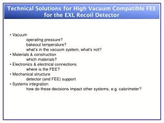
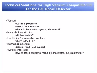
Technical Solutions for High Vacuum Compatible FEE for the EXL Recoil Detector • Vacuum • operating pressure? • bakeout temperature? • what’s in the vacuum system, what’s not? • Materials & construction • which materials? • Electronics & electrical connections • where is the FEE? • Mechanical structure • detector (and FEE) support • Systems integration • how do these decisions impact other systems, e.g. calorimeter?
Advanced Implantation Detector Array (AIDA): Update & Issues presented by Tom Davinson on behalf of the AIDA collaboration (Edinburgh – Liverpool – STFC DL & RAL) Tom Davinson School of Physics The University of Edinburgh
DESPEC: Implantation DSSD Concept • SuperFRS, Low Energy Branch (LEB) • Exotic nuclei – energies ~ 50 – 200MeV/u • Implanted into multi-plane, highly segmented DSSD array • Implant – decay correlations • Multi-GeV DSSD implantation events • Observe subsequent p, 2p, a, b, g, bp, bn … decays • Measure half lives, branching ratios, decay energies … • Tag interesting events for gamma and neutron detector arrays
Implantation DSSD Configurations • Two configurations proposed: • 8cm x 24cm • “cocktail” mode • many isotopes measured simultaneously • b) 8cm x 8cm • high efficiency mode • concentrate on particular isotope(s)
AIDA: DSSD Array Design courtesy B.Rubio • 8cm x 8cm DSSDs • common wafer design for 8cm x 24cm and 8cm x 8cm configurations • 8cm x 24cm • 3 adjacent wafers – horizontal strips series bonded • 128 p+n junction strips, 128 n+n ohmic strips per wafer • strip pitch 625mm • wafer thickness 1mm • DE, Veto and up to 6 intermediate planes • 4096 channels (8cm x 24cm) • overall package sizes (silicon, PCB, connectors, enclosure … ) • ~ 10cm x 26cm x 4cm or ~ 10cm x 10cm x 4cm
Implantation – Decay Correlation • DSSD strips identify where (x,y) and when (t0) ions implanted • Correlate with upstream detectors to identify implanted ion type • Correlate with subsequent decay(s) at same position (x,y) at times t1(,t2, …) • Observation of a series of correlations enables determination of energy • distribution and half-life of radioactive decay • Require average time between implants at position (x,y) >> decay half-life • depends on DSSD segmentation and implantation rate/profile • Implantation profile • sx ~ sy ~ 2cm, sz ~ 1mm • Implantation rate (8cm x 24cm) ~ 10kHz, ~ kHz per isotope (say) • Longest half life to be observed ~ seconds • Implies quasi-pixel dimensions ~ 0.5mm x 0.5mm
ASIC Design Requirements Selectable gain 20 100020000 MeV FSR Low noise 12 60050000 keV FWHM energy measurement of implantation and decay events Selectable threshold < 0.25 – 10% FSR observe and measure low energy b, b detection efficiency Integral non-linearity < 0.1% and differential non-linearity < 2% for > 95% FSR spectrum analysis, calibration, threshold determination Autonomous overload detection & recovery ~ ms observe and measure fast implantation – decay correlations Nominal signal processing time < 10ms observe and measure fast decay – decay correlations Receive (transmit) timestamp data correlate events with data from other detector systems Timing trigger for coincidences with other detector systems DAQ rate management, neutron ToF
AIDA: Resources & Tasks • Cost • Total announced value proposal £1.96M • Support Manpower • CCLRC DL c. 4.2 SY FEE PCB Design • DAQ h/w & s/w • CCLRC RAL c. 3.5 SY ASIC Design & simulation • ASIC Production • Edinburgh/Liverpool c. 4.5 SY DSSD Design & production • FEE PCB production • Mechanical housing/support • Platform grant support CCLRC DL/Edinburgh/Liverpool
Schematic of Prototype ASIC Functionality • Note – prototype ASIC will also evaluate use of digital signal processing • Potential advantages • decay – decay correlations to ~ 200ns • pulse shape analysis • ballistic deficit correction
Diagram (above) of the FEE boards as they would fit in the vertical plane. The grey rectangles are heat conductive foam pads which conform to the component outlines and conduct the heat to the water cooled metalwork. The green is pcb, the orange is a Samtec 80 pin connector with a 2.3mm height and the dark brown is the ASIC. The connections to the detector will be on the mezzanine boards to the left and to the acquisition network computers and BUTIS on the right. These are not shown. Diagram ( alongside) shows the layout of a sub-board.
AIDA Project Information Project web site http://www.ph.ed.ac.uk/~td/AIDA/welcome.html Design Documents http://www.ph.ed.ac.uk/~td/AIDA/Design/design.html Project Technical Specification ASIC Project Specification v1.3 FEE Specification v0.5 The University of Edinburgh (lead RO) Phil Woods et al. The University of Liverpool Rob Page et al. STFC DL & RAL John Simpson et al. Project Manager: Tom Davinson
Acknowledgements This presentation includes material from other people Thanks to: Ian Lazarus & Patrick Coleman-Smith (STFC DL) Steve Thomas (STFC RAL) Dave Seddon & Rob Page (University of Liverpool) Berta Rubio (IFIC, CSIC University of Valencia)
Representative ASIC Noise Analysis Note – amongst other assumptions, we assume detector cooling • Minimise ballistic deficit • shaping time >10x tr • operate with t ~ ms • noise dominated by leakage current for ID > 10 nA
Mechanical Design • STFC Daresbury Laboratory • professional 3D CAD/CAE engineering effort available • Propose STFC Daresbury Laboratory should be responsible for • mechanical design of • RISING (cluster detectors) array supports and stand • 4p Neutron detector stand/overall mechanical design of detector • TAS stand/overall mechanical design of detector • Fast Timing Array • Collaboration remains responsible for detector specification • STFC DL responsible for ensuring everything fits! • Assuming UK NUSTAR bid to STFC successful funds available for • stand construction, shipping and installation at GSI
AIDA: Current Status • DSSD request for tender • prototypes available 2008/Q3 • Prototype ASIC design • meeting design specifications • submission 2008/Q2 • FEE design underway • prototype available 2008/Q3 • liquid cooling required (cf. AGATA digitiser module) • Prototype testing • fully instrumented 8cm x 8cm DSSD • test experiments being considered for 2009
AIDA: Current Status • Evaluating • 10nF/100V capacitor arrays • long duration operation @ 400V • Analog Devices AD9252 14-bit/50MSPS ADC • FEE sampling ADC • DSSD response high energy heavy-ions • simulations Luigi Bardelli et al. • Texas A&M - November 2008 • MSL type W1(DS)-1000 34MeV/u 32Cl tr =100ns • GSI (100MeV/u) - March 2008? • higher energy, heavier ions predict tr > 400ns
Time Jitter • Transient signal analysis currently underway (realistic comparator design) • Preamplifier risetime ( Cf=0.6pF ) tr=110ns • LLD threshold 0.26% 20MeV FSR • 20MeV signal • jitter ~0.13ns rms ( ID=1nA ), ?ns rms ( ID=100nA ) • 0.2MeV signal • jitter ~2.7ns rms ( ID=1nA ), ~4.0ns rms ( ID=100nA ) • b events will normally trigger multiple strips ‘simultaneously’ • S/N improves as n1/2 • Highlights importance of • minimising detector – instrumentation separation • reduces noise and risetime • radiation damage mitigation • detector cooling
Outstanding Issues: approaching the Rubicon • Package size • 10cm x 26cm x 4cm (10cm x 10cm x 4cm) • Mechanical design concepts • 10cm x 26cm AIDA/ToF/Ge • 10cm x 26cm?? AIDA/4p Neutron Detector • 10cm x 10cm AIDA/TAS • … others? • Review ASIC Project Specification • DESPEC project requirements satisfied?