HUMIDITY SENSORS
HUMIDITY SENSORS. Sümeyra Likoğlu 50061103. Basics - 1.

HUMIDITY SENSORS
E N D
Presentation Transcript
HUMIDITY SENSORS Sümeyra Likoğlu 50061103
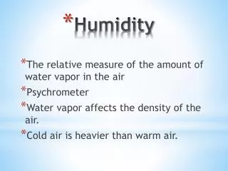
Basics - 1 • Humidity is the presence of water in air. The amount of water vapor in air can affect human comfort as well as many manufacturing processes in industries. The presence of water vapor also influences various physical, chemical, and biological processes. • Humidity measurement in industries is critical because it may affect the business cost of the product and the health and safety of the personnel. • Hence, humidity sensing is very important, especially in the control systems for industrial processes and human comfort.
Basics - 2 • Controlling or monitoring humidity is of paramount importance in many industrial & domestic applications. • In semiconductor industry, humidity or moisture levels needs to be properly controlled & monitored during wafer processing. • In medical applications, humidity control is required for respiratory equipments, sterilizers, incubators, pharmaceutical processing, and biological products. • Humidity control is also necessary in chemical gas purification, dryers, ovens, film desiccation, paper and textile production, and food processing.
Basics - 3 • In agriculture, measurement of humidity is important for plantation protection (dew prevention), soil moisture monitoring, etc. • For domestic applications, humidity control is required for living environment in buildings, cooking control for microwave ovens, etc. • In all such applications and many others, humidity sensors are employed to provide an indication of the moisture levels in the environment.
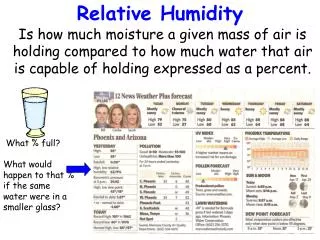
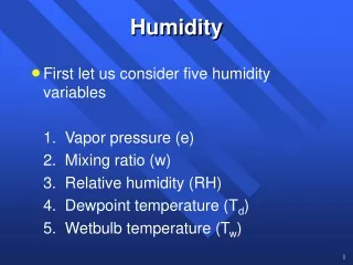
Classification of Humidity Sensor • Humidity measurement determines the amount of watervapor present in a gas that can be a mixture, such asair, or a pure gas, such as nitrogen or argon. • Most commonly used units for humidity measurement are Relative Humidity (RH), Dew/Frost point (D/F PT) and Parts Per Million (PPM). • RH is a function of temperature, and thus it is a relative measurement. Dew/Frost point is a function of the pressure of the gas but is independent of temperature and is therefore defined as absolute humidity measurement. PPM is also an absolute measurement.
Relative Humidity (RH) is the ratio of the partial pressureof water vapor present in a gas to the saturation vapor pressure of the gas at a given temperature. • Dew point is the temperature (above 0 C) at which the watervapor in a gas condenses to liquid water. Frost point is thetemperature (below 0 C) at which the vapor condenses toice. • According to the measurement units, humidity sensors are divided into twotypes: Relative humidity (RH) sensors and absolute humidity (moisture) sensors.
Relative Humidity Sensors • Relativehumidity sensorsareclassified intoceramic, semiconductor, and polymer humidity sensors. CeramicSensingMaterial • Humidity sensors based on water-phase protonic ceramicmaterials are used widely in industry and research laboratories. • The adsorbed water condensed on the surface ofthe materials and protons will be conducted in the formedaquaticlayers. • For ionic sensing materials, if the humidityincreases, the conductivity decreases and the dielectricconstantincreases.
In bulk water, proton is the dominantcarrier responsible for the electrical conductivity. The conductionis due to the Grotthuss mechanism, through whichprotons tunnel from one water molecule to the next viahydrogen bonding that universally exists in liquid-phasewater (Fig.1) Figure1: BrifillustrationGrotthussmechanism.
As shown in Figure 2, at the first stage of adsorption, a water moleculeis chemically adsorbed on an activated site (a) to forman adsorption complex (b), which subsequently transfersto surface hydroxyl groups (c). Then, another water moleculecomes to be adsorbed through hydrogen bonding onthe two neighboring hydroxyl groups as shown in (d). Figure 2: Fourstages of the adsorption
The top water molecule condensed cannot move freelydue to the restriction from the two hydrogen bonding(Fig. 2(d)). • Thus this layer or the first physically-adsorbedlayer is immobile and there are not hydrogen bonds formedbetween the water molecules in this layer. Therefore, noproton could be conducted in this stage. • As water continues to condense on the surface of theceramic, an extra layer on top of the first physicallyadsorbedlayer forms (Fig. 3). This layer is less orderedthan the firstphysically-adsorbed. Forexample, theremay be only one hydrogen bond locally.
Ifmorelayerscondense, the ordering from the initial surface may graduallydisappear and protons may have more and morefreedom to move inside the condensed water through theGrotthussmechanism. • Thismechanismindicates that sensors based purely on water-phase protonicconduction would not be quite sensitive to low humidity,at which the water vapor could rarely form continuousmobile layers on the sensor surface. Figure 3: Multi-layerstructure of condensedwater.
The two immobile layers, the chemisorbed and thefirst physisorbed ones, while cannot contribute to proton -conductingactivity, could provide electron tunnellingbetweendonorwatersites. • The tunnellingeffect, alongwith the energy induced by the surface anions, facilitateselectrons to hop along the surface that is covered by theimmobile layers and therefore contributes to the conductivity. • This mechanism is quite helpful for detecting lowhumidity levels, at which there is not effective protonicconduction.
SemiconductingSensingMaterials • H2O is adsorbed on the oxide surface in molecular andhydroxyl forms. Water molecules are increase theconductivity of n-type ceramics and to decrease theconductivity of p-typeceramics. • Thiseffect has beenattributed to the donation of electrons from the chemicallyadsorbed water molecules to the ceramic surface. • Water molecules replace the previously adsorbed andionized oxygen (O−, O2−, etc.) and therefore releasethe electrons from the ionized oxygen.Probably the“donor effect” could be resulted from both.
Because the conductivity is caused by the surfaceconcentration of electrons, this sensing style is usuallycalled “electronictype.” • The waterlayerformedby the physical adsorption may be somewhat proton-conductive.Therefore, at room temperatures the conductivityof ceramic semiconducting materials is actually dueto addition of both electrons and protons (ionic), unless athigh temperatures (>100 C) moisture cannot effectivelycondense on the surface. • In Figure 4a, the conductivityincrement is produced by surface electron accumulationresulting from the preferential alignment of the waterdipoles.
In Figure 4b, a depletion region forms originally due toadsorbed oxygen and the released electrons may neutralizethe depletion. Since adsorbed water molecules increasethe conductivity of n-type ceramic semiconductors. Figure 4: Two possible mechanisms for the “donor effect” (just forn-type): (a)Electrons are attracted by the adsorbed water molecules tothe semiconductor surface and the energy bands are bended; (b) Electronsare released by the competitive adsorption.
Polymer-Based Humidity Sensors • Organic polymers are macromolecules in which a unitstructure repeats. Most of the polymers are carbon-hydridecompoundsortheirderivatives. • Polymeric humidity sensors have been widelystudied in research and applied in industry for more than 30 years. • Most of the sensors are based on porous polymerfilms thinner than millimeters and their sensing principleis quite similar to that of ceramic sensors. • The film is filledwith micro-pores for water vapor condensation and someof the measurable physical properties change due to thewaterabsorption.
Traditionally, according to sensing mechanisms,polymerichumidity sensors are divided into two fundamentalcategories: resistive-typeandcapacitive-type. • Almost all of the humiditysensors based on polymers operate at room temperature,due to polymers’ high sensitivity to heat. Figure 5: Polymeric humidity sensors
Sensors based on capacitive effect: • Humidity sensors relying on this principle consists of a hygroscopic dielectric material sandwiched between a pair of electrodes forming a small capacitor. • In absence of moisture, the dielectric constant of the hygroscopic dielectric material and the sensor geometry determine the value of capacitance. • At normal room temperature, the dielectric constant of water vapor has a value of about 80, a value much larger than the constant of the sensor dielectric material. Therefore, absorption of water vapor by the sensor results in an increase in sensor capacitance.
Basic structure of capacitive type humidity sensor is shown below: Figure 6: Capacitivetypehumiddity sensor • On Alumina substrate, lower electrode is formed using gold, platinum or other material. A polymer layer such as PVA is deposited on the electrode. This layers senses humidity.
On top of this polymer film, gold layer is deposited which acts as top electrode. The top electrode also allows water vapour to pass through it, into the sensing layer . • The vapors enter or leave the hygroscopic sensing layer until the vapour content is in equilibrium with the ambient air or gas.Thus capacitive type sensor is basically a capacitor with humidity sensitive polymer film as the dielectric. Sensors based on Resistive effect: • Resistive type humidity sensors pick up changes in the resistance value of the sensor element in response to the change in the humidity. Basic structure of resistive type humidity sensor is shown in Fig. 7.
Figure 7: Resistivetype humidity sensor • Thick film conductor of precious metals like gold, ruthenium oxide is printed and calcinated in the shape of the comb to form an electrode. • Then a polymeric film is applied on the electrode; the film acts as a humidity sensing film due to the existence of movable ions. Change in impedance occurs due to the change in the number of movable ions.
ProsandCons of Capacitive-Resistive Humidity Sensors: • Capactive type sensors are very linear and hence can measure RH from 0% to 100%, but require complex circuit and also need regular calibration. • Resistive type sensors find difficulty in measuring low values (below 5%RH) , the change is impedance is too high and hence it is difficult to control the dynamics, temperature effects the properties significantly. • However, advances in electronics can mitigate the problems of temperature effects and high impedance change.
Capacitive RH sensors dominate both atmospheric and process measurements and are the only types of full-range RH measuring devices capable of operating accurately down to 0% RH. • Because of their low temperature effect, they are often used over wide temperature ranges without active temperature compensation. • Thermoset polymer-based capacitive sensors, as opposed to thermoplastic-based capacitive sensors, allow higher operating temperatures and provide better resistivity against chemical liquids and vapors such as isopropyl, benzene, toluene, formaldehydes, oils, common cleaning agents, etc.
Absolute Humidity Sensors(Hygrometers) • In early years, meteorologists were interested in an instrumentcapable of measuring the water content of the upperair latitudes where the water concentration was less than10 ppmv at air temperature of −56 C. • In 1948, a dew/frost hygrometer based on moisture condensation ona mirror was developed to measure the absolute humidityin extremely dry air of stratosphere with the lowestdetectable humidity level of −90 C frost point.
In 1967, a fully automated dew/frost point hygrometer based ona mirror with much better performance was developedwithmuchfasterresponse. • In 1978, a solid-state moisture sensor based on porous anodic aluminum oxide wasdeveloped with fast response and wide measurement range (−110 C to +50 C). Mirror-Based Dew/FrostPoint Sensors (Hygrometers) • The basic structure of a dew/frost hygrometer is shown in Figure 8. • Light from the Farmer electric lamp isprojected onto the sensing element and is received by thephoto resistor. If water condenses on the gold mirror ofthe sensing element, the photo resistor picks up the opticalsignal and the corresponding temperature is recorded.
Despite of their wide use, optical dew point hygrometershave several drawbacks including high cost, frequentmirror contamination, and instability under continuous use. • Dew point hygrometers based on direct mass measurementsof condensation have the potential to provide moreaccurate dew point measurement with high resolution. • Surfaceacoustic wave (SAW) devices have been used ashighlysensitivegas sensors. • SAW devices increase considerably the accuracy ofhumidity measurement because of their dual ability to detect dew condensation and to measure the temperaturewith a greataccuracy.
The experimental SAW device iscooled using a Peltier device. When water vapor condensationappears on the Rayleigh wave propagation path, itinduces a substantial attenuation of the wave amplitudeand a shift in the associate oscillator’s frequency (massloading). • Figure 9 shows a schematic of a SAW devicebased on a quartz substrate. The quartz cut was an LSTcutbecause of its high thermal sensitivity and good linearity. Figure 9: The experimental surface acoustic wave delay line configuration.
The SAW device was placed in an oscillator loop. Thequartz plate was cooled by means of a Peltier device gluedon the bottom face (Fig. 10) in order to condense thewater vapor on the SAW propagation path. • The amplitude depends minimally on the temperaturewhile decreases rapidly when sufficient water vapor condenses on the quartzplate. Figure 10: Principle of an acoustic wave dew point sensor.
The hot side of the Peltier element was water cooled. • This effect depends on thedew thickness/acoustic wavelength ratio. The frequencymeasurement was used for detecting dew deposition. AluminumOxide Moisture Sensors • Onlyaluminumoxide thin film sensor can be used for absolute humidity measurement. • As shown in Figure 11, sensor is basically a capacitor-likestructure consisting of a bottom aluminum electrode, ananodized porous Al2O3 film, and a thin, water permeablegold top electrode.
Based on an equivalentcircuit model,161 the porous Al2O3 film capacitive sensor is represented by parallel resistance and capacitance. Figure 11: Two types of moisture sensors.
When water vapor is transported through the permeablegold layer and equilibrates on the pore walls, the numberof water molecules absorbed on the pore determines thetotal complex impedence of the sensor. • The “meterreading” is proportional to the admittance of the sensor. As the moisturelevel decreases, the admittance decreases. • At a givenpressure, there is a one to one correspondence between thedew/frost point and the parts per million of water vapor.
References • http://www.engineersgarage.com/articles/humidity-sensor?page=1 • ZhiChen, ChiLu, “Humidity Sensors: A Review ofMaterialsandMechanisms”, Sensor Letters, 2005. • http://www.ehow.com/how-does_5306344_humidity-sensor-work.html