Download
1 / 13
130 likes | 176 Vues
Explore the use of Lorentz Cavities and Inner Volume Elements for calculating induced fields inside a cavity in organic molecular single crystals. Understand the contributions to shielding and demagnetization factors for accurate field measurements.

E N D
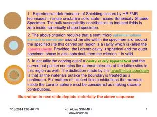
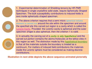
1. Experimental determination of Shielding tensors by HR PMR techniques in single crystalline solid state, require Spherically Shaped Specimen. The bulk susceptibility contributions to induced fields is zero inside spherically shaped specimen. 2. The above criterion requires that a semi micro spherical volume element is carved out around the site within the specimen and around the specified site this carved out region is a cavity which is called the Lorentz Cavity. Provided the Lorentz cavity is spherical and the outer specimen shape is also spherical, then the criterion 1 is valid. 3. In actuality the carving out of a cavity is only hypothetical and the carved out portion contains the atoms/molecules at the lattice sites in this region as well. The distinction made by this hypothetical boundary is that all the materials outside the boundary is treated as a continuum. For matters of induced field contributions the materials inside the Lorentz sphere must be considered as making discrete contributions. Illustration in next slide depicts the above sequence animated pictorially
The task would be to calculate the induced field inside the cavity σcavity Organic Molecular single crystal : a specimen of arbitrary shape Induced field calculation by discrete summation σinter I.V.E Sphere Continuum σIVE = σinter + σM Discrete I.V.E. Cavity Added σinter Shifts the line position O σcavity = σBulk +σM InnerVolume Element I.V.E H O σintra / σM O O 4 point star indicates the molecule at a central location. Structure of a typical molecule on the right σIVE(S) σM O H In-homogeneity can cause line shape alterations: O Proton Site with σintra not simply shifts only single sharp line
1. Contributions to Induced Fields at a POINT within the Magnetized Material. Equation for Discrete summation Discrete summation: an animated Illustration in Slides # 8 & 9 !!! The Outer Continuum in the Magnetized Material Inner Volume Element Sphere of Lorentz Specified Proton Site Lorentz Sphere Lorentz Cavity The Outer Continuum in the Magnetized Material Inner Cavity surface Din In the NEXT Slides: INDUCED FIELDS,DEMAGNETIZATION, SHIELDING::Current lessons on I.V.E. Outer surface D out D out = -Din HenceD out + Din =0 The various demarcations in an Organic Molecular Single Crystalline Spherical specimen required to Calculate the Contributions to the induced Fields at the specified site. D out/in values stand for the corresponding Demagnetization Factors MRSFall 2006/This slide 01m:15s for prev. 2 slides=02m:42s
INDUCED FIELDS,DEMAGNETIZATION,SHIELDING Induced Field inside a hypothetical Lorentz’ cavity within a specimen = H`` Shielding Factor = Demagnetization Factor = Da H`` = - . H0 = - 4 . . (Din- Dout)a . . H0 out These are Ellipsoids of Revolution and the three dimensional perspectives are imperative in = 4 . . (Din- Dout)a . When inner & outer shapes are spherical polar axis ‘a’ Din= Dout m = a/b Induced Field H`` = 0 equatorial axis ‘b’ Induced Field /4 . . . H0 = 0.333 - Dellipsoid Thus it can be seen that the the ‘D’-factor value depends only on that particular enclosing-surface shape ‘innner’ or ‘outer’ = b/a polar axis ‘b’ equatorial axis ‘a’ References to ellipsoids are as per the Known conventions-------->>>> MRSFall 2006/This slide 01m:30s for prev. 3 slides=03m:57s
RECAPITULATION on TOPICS in SOLID STATE Defining what is Conventionally known as “Lorentz Sphere” It becomes necessary to define anInner Volume Element [I.V.E] in most of the contexts to distinguish the nearest neighbours (Discrete Region) of a specified site in solids, from the farther elements which can be clubbed in to be a continuum. The shape of the I.V.E. had always been preferentially (Lorentz) sphere. But, in the contexts to be addressed hence forth the I.V.E. need not be invariably a sphere.Even ellipsoidal I.V.E. or any general shape has to be considered and for the sake of continuity of terms used it may be referred to as Lorentz Ellipsoids / Lorentz Volume Elements. It has to be preferred to refer to hence forth as I.V.E. ( Volume element inside the solid material : small compared to macroscopic sizes and large enough compared to molecular sizes and intermolecular distances). I.V.E. need not be invariably a sphere general shape Currently:The Discrete Region Conventional Lorentz Spheres I.V.E. Shapes other than spherical For any given shape For outer shapes OR arbitrary Spherical cubical OR ellipsoidal OR MRSFall 2006/This slide 02m:01s for prev. 4 slides=05m:27s
The task would be to calculate the induced field inside the cavity σcavity Organic Molecular single crystal : a specimen of arbitrary shape Induced field calculation by discrete summation σinter I.V.E Sphere Continuum σIVE = σinter + σM Discrete I.V.E. Cavity Added σinter Shifts the line position O σcavity = σBulk +σM InnerVolume Element I.V.E H O σintra / σM O O 4 point star indicates the molecule at a central location. Structure of a typical molecule on the right σIVE(S) σM O H In-homogeneity can cause line shape alterations: O Proton Site with σintra not simply shifts only single sharp line
Line (position) shifts & Line shape changes NMR Line for only Intra molecular Shielding σ=‘σM’ Added intermolecular : σInterContributions causes a shiftdownfieldorup field σ = ‘σM’+‘σInter’ ’+‘σB (homogeneous)’ Homogeneousnoline shape alterations Slightly inhomogeneous Nearly spherical & shifted & shifted Cylindrical Highly inhomogeneous Inhomogeneous Magnetization can cause line shape alterationsσ = ‘σM’+‘σInter’ ’+‘σB(in-homogeneous)’
1. Contributions to Induced Fields at a POINT within the Magnetized Material. Equation for Discrete summation Discrete summation: an animated Illustration in Slides # 8 & 9 !!! The Outer Continuum in the Magnetized Material Inner Volume Element Sphere of Lorentz Specified Proton Site Lorentz Sphere Lorentz Cavity The Outer Continuum in the Magnetized Material Inner Cavity surface Din In the NEXT Slides: INDUCED FIELDS,DEMAGNETIZATION, SHIELDING::Current lessons on I.V.E. Outer surface D out D out = -Din HenceD out + Din =0 The various demarcations in an Organic Molecular Single Crystalline Spherical specimen required to Calculate the Contributions to the induced Fields at the specified site. D out/in values stand for the corresponding Demagnetization Factors MRSFall 2006/This slide 01m:15s for prev. 2 slides=02m:42s
2. Calculation of induced field with the Magnetic Dipole Model using point dipole approximations. Induced field Calculations using these equations and the magnetic dipole model have been simple enough when the summation procedures were applied as described in the previous presentations and expositions. Isotropic Susceptibility Tensor =
2. Calculation of induced field with the Magnetic Dipole Model using point dipole approximations rs v = Volume Susceptibility r V = Volume = (4/3) rs3 2 1 v= -2.855 x 10⁻⁷ rs/r= 45.8602=‘C’ 1= 2 = 2.4 x 10⁻¹¹ for =0
2. Calculation of induced field with the Magnetic Dipole Model using point dipole approximations For the Point Dipole Approximation to be valid practical criteria had been that the ratio r : rS= 10:1 Ri : ri = 10 : 1 or even better and the ratio Ri / ri = ‘C’can be kept constant for all the ‘n’ spheres along the line (radial vector) ‘n’ th iwill be the same for all ‘i’ , i= 1,n and the value of ‘n’ can be obtained from the equation below 1st With “C= Ri / ri , i=1,n” 3. Summation procedure for Induced Field Contribution within the specimen from the bulk of the sample.
Description of a Procedure for Evaluating the Induced Field Contributions from the Bulk of the Medium Radial Vector with polar coordinates: r, θ, φ.(Details to find in 4th Alpine Conference on SSNMR presentation Sheets 6-8) http://nehuacin.tripod.com/id1.html
For a given and , Rn and R1 are to be calculated and using the formula “n” along that vector can be calculated with a set constant “C” and the equation below indicates for a given and this ‘n,’ multiplied by the ‘i’ { being the same for all }would give the total cotribution from that direction = i = i=1,n,i = n, x i