Low frequency RS485 interfaces
Low frequency RS485 interfaces. J.-D. Chatelain. RWM 1. RWM 2. RWM 3. RWM 4. RWM 2. RWM 3. RWM 4. RWM 1. RWM 1. Interface 1. Interface 2. Interface 3. Power supply. Fieldbus. Reference Rx Tx(PC) Tx Rx(PC). 1. 0. RS485 Interfaces - Internal connector. Power supply

Low frequency RS485 interfaces
E N D
Presentation Transcript
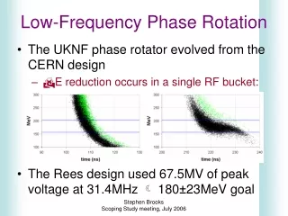
Low frequency RS485 interfaces J.-D. Chatelain
RWM 1 RWM 2 RWM 3 RWM 4 RWM 2 RWM 3 RWM 4 RWM 1 RWM 1 Interface 1 Interface 2 Interface 3 Power supply Fieldbus
Reference Rx Tx(PC) Tx Rx(PC) 1 0 RS485 Interfaces - Internal connector Power supply Differential voltage Differential voltage for Input Ground for housing ÷ Reference Differential voltage for Outputs DIP-switch Address selection Output 1 Output 2 Output 3 Output 4 Reference A B V+ref V-ref IN+ IN- V+ V- GND 5V RS485 RS232 Reset button Switch
RS485 Interfaces - Meaning of the LEDs The interface is powered RWM 2 is correctly connected All the possibilities are programed by means of the configuration display or the CF command There are many possibilities to program the OUTPUTs. One of them is tosetthe OUTPUT when a transponder is present in front of the corresponding RWM A transponder is in front of RWM 2 There is a communication problem with RWM 2 RWM 2 is communicating with the transponder RWM 2 is communicating with the transponder Now, there are transponders in front of RWM 2, 3 and 4 Another possibility is toclearthe OUTPUT when a transponder is present in front of the corresponding RWM
These are the codes obtained when reading the outputs(Command OR) or the codes entered to force the outputs (Command OW). RS485 Interfaces - Coding the OUTPUTs 00 01 02 03 04 05 06 07 08 09 10 11 12 13 14 15
Low frequency RS485 interfaces End of this chapter J.-D. Chatelain