Download
1 / 2
30 likes | 222 Vues
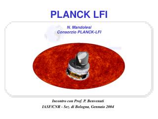
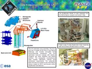
Low Frequency Instrument (LFI). The Qualification Model LFI after integration into the Alenia-Spazio cryogenic test facility in Italy. A flight model 70 GHz Radiometer Chain Assembly under test at Electro-Bit Microwave in Finland.

E N D
Low Frequency Instrument (LFI) The Qualification Model LFI after integration into the Alenia-Spazio cryogenic test facility in Italy. A flight model 70 GHz Radiometer Chain Assembly under test at Electro-Bit Microwave in Finland. The LFI radiometer array assembly. The front-end unit is located at the focus of the Planck telescope, and includes corrugated feed horns,orthomode transducers, and the radiometer front-end modules with hybrids, cryogenic low noise amplifiers and phase switches. The waveguides simultaneously meet complex radiometric, thermal and mechanical requirements. The radiometer back-end units are located on top of the Planck service module at 300 K and provide further amplification and detection.
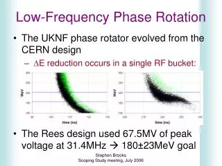
Main LFI flight performance specifications The LFI is being designed and built by a Consortium of scientists led by Reno Mandolesi of the Istituto Fisica Spaziale e Fisica Cosmica (IASF) in Bologna (Italy). The other main institutes involved in the LFI Consortium are:Chalmers University of Technology,(S),Danish Space Research Institute (DK), Instituto de Astrofisica de Canarias,(E), Instituto de Fisica de Cantabria (E), Istituto CAISMI(I), Istituto IASF (CNR)(I), Istituto di Fisica del Plasma IFP (CNR)(I), Istituto IFSI(I), Jet Propulsion Laboratory,(USA), Max-Planck-Institut fuer Astrophysik(D), Millimetre Wave Laboratory(FI) Jodrell Bank Observatory(UK), Osservatorio Astronomico di Padova(I), Osservatorio Astronomico di Trieste, SISSA(I), Space Science Dpt of ESA(NL), Theoretical Astrophysics Center(DK), University of California (Berkeley)(USA), University of California (Santa Barbara)(USA), Universite de Geneve(CH), University of Oslo(N), Universita Tor Vergata(I) LFI Beams (HFI beams fill the central region) Crosses indicate orientation of receiver polarization LFI “Continuous Comparison” Pseudo-correlation receiver. One phase switch switches at 8192 Hz, providing alter-nately ‘Sky’ and 4 K ‘Reference’ outputs at each diode. Differencing these states effectively removes 1/f noise from the data. Picture of the 30 GHz Radiometer Chain Assembly being mounted in the RCA cryo testchamber at Alenia Spazio, Italy. The four waveguides are visible, the twisted copper section connected to the 20 K Front End Module, and the straight stainless steel section connecting to the 300 K Back-End Module. The horn feeds two radiometers, each carrying one of the linearly polarised components provided by an Ortho Mode Transducer.