Download
1 / 39
390 likes | 508 Vues
CMS MU IB chairs D.Reeder ( M.Cerrada ) P.Managers F.Gasparini G.Mitselmakher I.B. Chairs D.Reeder M.Cerrada R.Manager C.Peroni Tech. Coords H.Reithler R.Loveless Task Coords . G.Iaselli (rpc) T.Rodrigo (alignment)

E N D
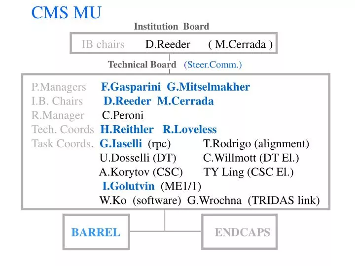
CMS MU IB chairs D.Reeder ( M.Cerrada ) P.ManagersF.Gasparini G.Mitselmakher I.B. ChairsD.Reeder M.Cerrada R.Manager C.Peroni Tech. CoordsH.Reithler R.Loveless Task Coords.G.Iaselli (rpc) T.Rodrigo (alignment) U.Dosselli (DT) C.Willmott (DT El.) A.Korytov (CSC) TY Ling (CSC El.) I.Golutvin (ME1/1) W.Ko (software) G.Wrochna (TRIDAS link) Institution Board Technical Board(Steer.Comm.) BARREL ENDCAPS
Project leader F.Gasparini Tech.Coord. H.Reithler SPO U.DosselliPlanning H.ReithlerSafety S.MaselliQA&QC D.DattolaIntegration G.Bencze Alignment G.IaselliRPC Technical Board Tech.coordin. H.Reithler DT chambers U.Dosselli DT electronics C.Willmott RPC G.Iaselli RPC electronics A.Ranieri Alignment T.Rodrigo, G.Bencze TRIDAS link G.Wrochna Software U.Gasparini Integration (detect.) D.Dattola (services) H.Reithler Resource Manager C.Peroni Finance Board M.Cerrada Spain D.Rein Germ. G.Zumerle Italy R.Loveless US V.Karjavin RDMS Drift Tubes Committee H.Reithler M.Cerrada C.Peroni A.Rossi U.Dosselli G.Zumerle C.Willmott BARREL muon
1) MU Identification 2) MU Level 1 Trigger with Threshold up to 100 GeV 3) MU measurement 1) is performed by4 Muon Stationslooking for particles penetrating through the large and segmented return Yoke of the CMS Magnet 2) bunch crossing Identification & fast standalone Pt measurement using precision chambers and fast RPCdetectors in each station 3) precision and redundancy :6 layers CSCin the Endcaps (1000 m2) 8 layers DRIFT TUBESin the Barrel (+4 layers)(1800 m2) fabrizio15/5/2000
THE BARREL MU long drift time tubes are cheaper than MWPC more sensitive to magnetic field,delta rays and e.m.showers use of cool gas (Ar/CO2),accurate field shaping (4 electrodes), many staggered layers redundancy generates robustness against neutron and e.m. background and allow prompt measurement of time , position and angle of passage of a track for MU trigger design requirement: reconstruction of tridimensional track segments/station within 150 micron in position and 1 mrad uncertainty in the bending plane this translates into: 8 layers in the bending and 4 layers in the non bending projection 300 precision/wire and an adequate lever arm/station .5 to 1 mm chamber positioning for efficient track identification 150 to 400 positioning for precise standalone Pt fabrizio15/5/2000
Magnetic and radiation environment (Barrel) Magnetic Field highly inhomogeneous can locally reach .8 T perpendicular to the wire plane (MB1) .3 T parallelto the wires (ch. borders&corners) neutron <104 Hz/cm2 (MB1 And MB4) (1010/cm2 in 10 years) absorbed dose << 1 Gy /10 yearsoperation in the worst case HIT rate < 10 Hz/cm2 (1 to 10 KHz/wire or RPC channel) collected charge . 5 C/cm of wire (1 hit=4*MIP,100 Hz/cm2,gain 10^5) fabrizio15/5/2000
BARREL MU INSTITUTES & LABORATORIES Aachen RWTH III A drift chambers Bari Univ.-INFN RPC Beijing IHEP drift chambers Bologna Univ.-INFN drift chambers CERN Mic - CMT drift chambers alignment CIEMAT drift chambers alignment Debrecen K.L.Univ. alignment Islamabad Opt.Lab. alignment Padova Univ.-INFN drift chambers Pavia Univ.-INFN RPC Peking Univ. RPC Santander IFCA-Univ. alignment Sofia INRNE RPC Sofia Univ. RPC Torino Univ.-INFN drift chambers Warsaw SoltanINS RPC Wien HEPHI alignment TECHNICAL COLLABORATIONS Protvino IHEP drift chambers Dubna JINR drift chambers fabrizio15/5/2000
2000 is a critical year: *volume procurement of raw materials *volume production of parts :mechanical & electrical **setting up of the assembly sites *preproduction of parts for chambers of 2000 *production of first chambers in three (/four) sites in 2000 **setting up of the sites for parts production *begin volume production of parts *design of tools for installation *preparation for the assembly of the Yoke wheels in 00 and 01 *tendering for volume production of TDC and Trigger electronics *2000 is the most expensive year , commitments/payments limited by the funding profile fabrizio15/5/2000
status : - chamber design is finished - design of tools for chambers finished - design of tools for parts finished - assembly/commissioning of tools is in good progress - first SLayers (MB2) assembled in Madrid with final tools - R&D of trigger electronics still going on - progress in HV and LV supplies - first samples of TDC available in July - radiation test is in progress and planned in view of ESR in Autumn fabrizio15/5/2000
DT Chambers Production sharing 4 3 5 2 6 1 7 12 8 9 11 10 Aachen Madrid Chambers that can’t be installed in SX Padova Torino
THE DT CHAMBERS (Z view) plates I-Beams MB4 MB1 200 ~ 400cm 27cm 250cm beam line Pads for RPC suspension HV& decoupl. Boards F-End Mini crates R-Out & Trigger Honeycomb & integrated C-Beams RPC and DT are inserted in the yokes as a unique body (constraint in prod. & install. Schedules) fabrizio15/5/2000
THE DT CHAMBERS (X,Y VIEW) plates I-Beams 250cm 27cm 3 MB4 2 MB1 200 ~ 400 cm Pads for RPC suspension HV& decoupl. Boards F-End Suspension rails screwed to the yoke Alignment LEDs/holders Suspension “scale” Honeycomb & integrated C-Beams fabrizio15/5/2000
S g C s a b W b/a ~ .65 continuous lines represent electrodesdotted lines represent equipotential surfaces the presence of the grounded Al plates and beams between S and C makes the position of the g equipotential quite independent of the Voltages of s and c Vc ( and Vs) must generate in the region between c and g ( and between g and s ) an E field between 1 and 2 KV/cm to saturate the drift velocity the position of the s equipotential depends on the cell geometry (i.e. on the strip width and on the wire radius) Vw-Vs determines the GAIN in the gas : the request of a gain of ~ 10^5 determines the position of the s equipotential to be ~ 2.5 mm from the wire fabrizio 28/3/00
For practical and safety reasons many components are inside the gas volume of the chamber An intensive campaign of measurements to identify possible aging effects from these materials was organized and done ( and will continue,for safety reasons,to check each delivery of materials): - glues on Mylar and Aluminum strips - bare HV,Decoupling and F-End Boards - cables & connectors - fully equipped boards Many components were investigated also after neutron irradiation (@ PROSPERO ,Valduc,F) - to look for effects from FR4. - for effects on structural glues (results are published ,or submitted, as CMS N.,IN.,scient.papers) fabrizio 28/3/00
AGING & IRRADIATION MEASUREMENTS: In the aging set up in LEGNARO: Aging measurement were performed on Mylar and Aluminium strips to be used for cathode and field shaping electrodes.Strips were tested with and without glue. No aging was detected for >10 LHC years. Pieces of I-Beams and Al .Plates to check for possible effects of cleaning solvents (I-Beams) and of surface treatment (plates). HV and Fend Boards with components&cables) No aging was detected. In the LEGNARO 7 MeV V.d.G. neutrons (6.5 MeV) and thermal n. contr.board+BTI+TSS 20 faults in 10 y of LHC F-End 300 hits in 10 y of LHC In nuclear reactors (Valduc,F. and in Spain) Glued samples and electronics components and boards Prototypes of HV (Caen) and LV (Crisa) supplies 5 * 10 ^ 12 neutrons/cm2 NO DAMAGE In magnetic field prototypes of LV supply up to 1 T POSITIVE With High energy neutrons (>20 MeV) Electronics and supplies will be tested against effects of neutrons up tp 70 MeV in the facility of the UNIVERSITE’ CATHOLIQUE de LOUVAIN in Belgium . Two beams are available with enegry tunable up to 65 MeV: -one with a broad,nearly flat,spectrum with 20 * 20 cm2 cross section,and an intensity of 3.6 * 10^7 n/cm2/sec -a second ,”monochromatic” and of few cm2 with intensity of 1.7 * 10^5 n/cm2/sec The first is ideal to test complete boards ,the second will be used to verify critical components The first run ,with the broad beam,is planned by the end of June 00. fabrizio15/5/2000
MECHANICAL TESTS: the chamber mockup was proven - to comply with seismic French rules - to be capable of supporting the RPC charge TEST BEAM ACTIVITY: (most significant) one prototype, 3 SL, 3*1 m2, put in GIF in 1987/98 for the equivalent of 6 to 8 LHC years the first MB2s will be put in the GIF this winter coupled to RB2 RPCs the first full chamber (MB96, a MB1 type) was in H2 in 97 and in the GIF,to test rate capability,in summer 98 a “final” SL (Q4) was in the magnet in the H2 beam in 99 (B parallel to the wires) and will be in 00 (B perpendicular) fabrizio15/5/2000
The smallest independent unit is the Super Layer chambers are built by gluing together three or two (MB4) SLs operations for the mechanicalassembly of one SL: 9 gluing operations/superlayer 9 w.days /superlayer glue 2 Workers + 1 Supervisor 9 7 6 5 4 3 2 8 1 fabrizio15/5/2000
CHAMBER ASSEMBLY BRICKS plates+strips Torino preprod.+Dubna mass prod. I-Beams+cathodes Bologna preprod+Protvino mass prod. H-Comb+C-beams firm preprod + firm mass prod. HV Boards Padova preprod+IHEP mass prod. F-Ends+Boards firm + minicrates [readout+trigger boards] preproduction allows the construction of few chambers during 2000 ~ 2MB1, 7 MB2, 5 MB3 fabrizio15/5/2000 Nov. 99
Plans and status assembly site # of tables type of chamber (#) ready in production Aachen 3 MB1 (70) June 2000 Sept. 2000 Legnaro 3 MB3 (70) MB4 (10) March 2000 May 2000 (Sept.2000) Madrid 3 MB2 (70) Jan.2000 May 2000 (1st MB2 SL: test) Torino 1 MB4 (30) fall 2000 Jan 2001 (Jul.2001) Volume production of plates (Dubna) Sept.2000 Oct. 2000 (shipment to) Volume production of I-Beams (Protvino) June 2000 Oct. 2000 (shipment to) HV and Decoupling Boards (IHEP) Dec. 1999 Volume production of F-Ends Jan. 2000 March 2000 (1st batch 10^4 June 00) Volume production of F-End Boards Jan. 2000 March 2000 (150 boards available from previous supplier (20.000 ch))(tender 4/00) (preserie Sept.00) Nov. 99 fabrizio15/5/2000
Assembly tools: Precision table for SL (plan.better 50 ) XY plotter (better than 50 ) Glue dispenser CCD camera (better than 20 ) I-Beams holder (better 100 ) Wiring machine Handling tools Ancillary tables for completion,electr.inst.,test Table for ch. Assembly fabrizio15/5/2000
y CCD Camera Glue dispenser In the tables for MB1 & 2 the A & B charriots are mech .coupled, for MB3 & 4 the coupl. is electric as in the big milling machines. Two different arrangement are used in To and Pd for the MB4 ch.s: the bridge of the X,Y plotter has different Orientations. A B MB2 MB1 Wires are along Z (PHI tables) z Padova Strip deposition plates saw: (22 types of plate) MB3 & MB4 Torino The I-beams tools for MB1 &2 become two heavy scaling to MB4. They are also different. Torino uses the same design for the three tables : the two for plates cutting and strips deposition and the one for MB4 assembly fabrizio15/5/2000
BRICKS STATUS: ITEM Mass prod. Preprod. First batch Drift Chambers H-Comb tendering (Jan.2000)ordered(av.June) Nov.00 I-Beams tendering (closing) done I-Beams assembly in Protvino area in preparation progress(Bo) Al Plates tendering (Jan.2000)available Al Plates assembly in Dubna area in preparation mar/april (Jun/Jul-To) HV Boards assembly in IHEP started done F-Ends in order done Jun.00 F-End boards tender in prep. (4/00) Minicrates ordered RPC Bakelite plates tendering (Jan.00) 400 tested Double gaps production tendering (Jan.00) F-End VLSI march 2000 (ESR pending) done/tested RPC fabrizio15/5/2000 Nov. 99
PLAN/STATUS OF I-BEAMS PRODUCTION (10/4/00) THETA MB1 THETA MB2 status where PHI THETA MB3 ready CIEMAT 944 458 reday Legnaro 1000 300 ready Bologna 500 10/4/00 Bologna 600 15/6/00 Bologna 1000 600 650 530 TOTAL 3444 900 1108 530 (~6000 beams produced in Bologna,tested in dry air,4.6 KV,< 1% rejection) 26/6/00 SHIPMENT of the first I-Beam assembly table&tools to Protvino Nov. 00 Protvino 8000 Nov. 00 Bologna 1000 650 Jan. 01 Bologna 2600 600 500 TOTAL ~ 11.350 in Bo. + 8.000 in Protvino Jan. 01 SHIPMENT to Protvino of the second table and tools, end of production in Bologna. fabrizio15/5/2000
The two basic bricks are the ALUMINIUM PLATES and the I-BEAMS Both hold FIELD SHAPING ELECTRODES made of Al 50 tape insulated with Mylar 100. The ribbons are deposited /inserted on the plates/beams in specialized labs, from which plates and beams are shipped to the assembly sites The expected production capability is 4000 beams and 100 plates in 10 days The needat the nominal overall Super Layer production rate of 10 SL in 10 days is of 2600 beams and 50 plates fabrizio15/5/2000
The performance of the drift tube is largely insensitive to the positioning of the field shaping strips and of the I-Beams on the plates, and on the position of the wires along the CMS R A tolerance of + - 500 micron was measured to be fully acceptable More demanding are: A) the wire pitch and staggering in PHI 42 + .1 mm ( for trigger purposes) B) the distance between the strip and Mylar along the border sides (for insulation ) 3 . 5 + .2 mm C) the distance between the strip and Mylar borders at the end of the electrodes (for insul.) 5 + .2 mm _ _ _ fabrizio15/5/2000
A), B) and C) were shown to be under control during the prototype construction. A) wire position : the design of the End plug in two parts makes the position of the wire independent of the the I-Beam position. The crimping block holding the wire sits in the part of the plug that self centers respect to two small plastic guiding pieces precisely glued on the plates in front of the I-Beams ends. B) for strips on the plates : Mylar and Aluminiun strips are put down in the same pass by the same machine,an on-board CCD camera check the borders during the deposition for the strips in the I-Beams: the very precise guidance of the deep I-Beam groove is exploited to ensure the ultimate precision in the strip insertion C) The Aluminium strips are cut with reference to the Aluminium plate or Beam end border (relative floating positioning) fabrizio15/5/2000
1 Barrel Mu chambers construction and CMS general schedule A) crew 1,2,3 9 days (glue and wire 3 SL, on tables 1,2,3) B) crew 4 (+1,2,3) 9 days (close&cable 3 SL) in the shadow of A) C) crew 4 (+physists) 9 days (test 3 SL) in the shadow of A) D) crew 1,2,3 3 days (glue 3 SLs , table 4) in the shadow of A) one crew 2 workers + 1 supervisor (total 9 to 12 persons for 4 tables) time for a chamber 9 days (with 4 tables) useful working days 176/year > holidays : Easter,Aug.,Christmas > refurb.,repair etc : 1 day out of 5 12 ~ 14 chambers/wheel must be installed in the UX (Assume 12) sector 1 and 7 2 MB1 (Aa) 2 MB2 (Ma) 2 MB3 (Pd) 2 MB4 (To,Pd) sector 2 and 6 2 MB3 (Pd) 2 MB4 (To,Pd) Install in Sx ch. produced 3 months before the dead line fabrizio15/5/2000
Construction and Installation schedules draft schedules are based on reasonable assumptions BUT : - the definition of “good” SL - the yield of “good” SLs - the time & efficiency for testing and repair “no good” SLs - the long term reliability and duty cycle of complicated tools - the problems of organization and management of a worldwide spread production of critical parts - the real need and availability of manpower will be known only in one year from now , in spring 2001 fabrizio 28/3/00
draft CONSTRUCTION draft A) Time for the full lot of chambers Aachen 70 * 9 (w. d./Ch.) /176 = 3.6 years (mid 04) Madrid 70 * 9 /176 = 3.6 years (mid 04) Padova 80 * 9 /176 = 4.1 years (beg. 05) Torino 30 * 20 /176 = 3.4 (+.5) y. (beg. 05) B) Time for prod. of chambers to be installed in SX last installation window in SX : April 2004after 3 years of prod. in 3 years : Aa 59 ch. , Ma 59 ch. , Pd 59 ch. , To 22 chambers Chamb./wheel to be installed in SX : 38 out of 50 (12~14 MUST be in UX) THE 38 => 10 MB1 (Aa) + 10 MB2 (Ma) + 8 MB3 (Pd) + 10 MB4 10 MB4 = 2 MB1 (feet,Aa) + 2MB2 (bottom,Ma) + 2 MB3 (top,Pd) + 4 MB4 (To) ch./wheel (5 wheels) Jan.04(Apr. 04) missing (-for full lot) Aachen 12 (60) 59/60 1 (11 MB1) Madrid 12 (60) 59/60 1 (11 MB2) Padova 10 (50) 59/50 1 (11 MB3,10 MB4) Torino 4 (20) 22/20 0 ( 8 MB4) fabrizio15/5/2000
draft INSTALLATION draft Chambers are installed in a wheel when the 38 DT and RPC of that wheel are available: constructed+shipped to ISR+tested+measured(Alignm.)+moved to P5 time for installation in a wheel: - services (gas/cooling/cables/balcony electronics) are ready - trigger and R-out electronics sitting on the chambers is installed - installation is : DT/RPC coupling, insertion, test of all connections (photogrammetry not included ,MAB cabling partially) time for install.of 38 ch. in SX => 1 Month (half a day/chamber) constraints: availability of electronics / DT <=> RPC schedule fabrizio15/5/2000
Active electronics placement in a BMU Station RPC DRIFT TUBE CHAMBER MAB Front ends MAB Readout/Trigger/Control Minicrate fabrizio15/5/2000
3) electronics: electronics is sitting on the chambers in each chamber of one CMS sector : 1 ROB (Read Out Board) 128 ch. 1 TRB (Trigger Board) 128 ch 4 TDC (any of them can act as Master) 32 BTI,4 TRACO,1 TSServer => precise coordinates=>2 best MU in the Board ONE TS Board houses the TSMaster (two parts,any can act as master) => 2 best MU in the chamber in the gas volume : F-End chips/boards & HV boards 32 F-End chips (2 Boards) feed: in the Minicrates : in the 4th station Sector collector board fabrizio15/5/2000 to the counting room
A=Amperes W=Watts DT POWER REQUIREMENTS: ONE CHAMBER ch. type (#) [sector] minicrates f-ends total(F-End) 3.3 V 5V 2.5V 5V A W A W A W A W W MB1 (60) [all] 26 86 1 5 4 10 2 10 111 (20) MB2 (60) [all] 29 96 1 5 4 10 2 10 121 (20) MB3 (60) [all] 34 112 1 5 5 13 2 10 140 (23) MB4 (30) [1,2,3,5,6,7] 34 112 1 5 5 13 2 10 140 (23) MB4 (10) [8,12] 34 112 1 5 4 10 2 10 137 (20) MB4 (10) [9,11] 20 66 1 5 2 5 1 5 81 (10) MB4 (5) [4left] 26 86 1 5 4 10 2 10 111 (20) MB4 (5) [4right] 29 96 1 5 4 10 2 10 121 (20) MB4 (5) [10left] 25 83 1 5 3 8 1 5 101 (13) MB4 (5) [10right] 25 83 1 5 3 8 1 5 101 (13) ALL CHAMBERS : MB1 TOTAL 1560 5160 60 300 240 600 120 600 6660 MB2 TOTAL 1740 5760 60 300 240 600 120 600 7260 MB3 TOTAL 2040 6720 60 300 300 780 120 600 8400 MB4 TOTAL 2085 6880 110 350 280 720 120 600 8550 GRAND TOTAL 7425 24520 290 1250 1060 2700 480 240031 KW fabrizio15/5/2000
This scheme is elegant and cheap but constrains together Electronics and Chambers Production: a) HV Boards and Fend should be available at the time the SUPERLAYER is built to check and commission it before the three Slayers of a CHAMBER are glued together b) Rout and Trigger Boards sit in minicrates inserted in the Hcomb before the chamber is installed fabrizio15/5/2000
a) the first final protos of Fends will be available by end Nov.99 OK 2000 chips for first ch.will be available OK Dec.99 (on loan from COMPASS exp.) tender for CMS mass prod.is at the latest days begin of mass prod.expected in spring 2000OK fabrizio15/5/2000
b) • the first ROB should be ready in spring 2001 and first minicrates in September 2001 • -we must allow for 6 months contingency in case s.t. goes wrong (orange dates) • -we need six month burn-in of electronics • in the minicrates (at ambient temperature ,now with standard procedures) • -chambers will be installed EQUIPPED with full electronics • chip status : (prod.=tender) • BTI ready prod . 6/2000 *(1/2001) • BTI mod. ready prod. 9/2000 *(3/2001) yield below 50% • TRACO under test (1/2001) (6/2001)lay out problems : 2 submiss.jun/jul 00 • TSS,TSM planned 1/2001 (id.) • TRB planned 3/2001 (9/2001) • TDC prod. end 2000 (6/2001) • ROB planned 3/2001 (9/2001) • minicrates planned 9/2001 (3/2002)expected date for availability • * common Tender at end 2000 :Market S. June • problems with $/CHF fabrizio15/5/2000
draft INSTALLATION draft Installation demands the presence of technicians & physicists to avoid spoiling the labs : => install all the ch. of a Wheel in one go => install ch. equipped with R-Out & Trigger electronics => choose a sequence that minimizes the impact of possible construction delays => tune the construction sequence accordingly (RPC included) => install in UX YB0 mid 02 * YB+1 beg. 03 YB-1 end 03 YB+-2 in the last window in 04 ( YB+-2 are the most easy to handle in SX ) * a earlier installation in YB0 without electronics may also be considered fabrizio15/5/2000
CURRENT CMS MASTER PLAN UP TO APRIL 2004 vers. 28 Modified 5/4/00 Windows for MU ch. Installation in SX (CMS SC march 20/00,under discussion) 2000 2001 2002 2003 2004 YB-2 YB-1 YB-0 YB+1 DT+RPC INSTALL. YB+2 YE-1,-2,-3 YE+1,+2,+3 Installation procedures/tools/times…..must be understood and agreed fabrizio 20/3/00 In green the wheels assembly windows (for supporting rails)
CURRENT CMS MASTER PLAN UP TO MARCH 2004 vers. 28 Windows for MU ch. Installation in UX (to be confirmed) 2004 2005 YB-2 YB-1 YB-0 YB+1 YB+2 YE-1,-2,-3 YE+1,+2,+3 fabrizio 20/3/00