Download
1 / 23
240 likes | 577 Vues
Improved Performance Of Diesel Driven Permanent Magnet Synchronous Generator Using Battery Energy Storage System. By JANE MARIA S Edited By Sarath S Nair www.technologyfuturae.com. OVERVIEW. Introduction Need of BESS Schematic block of BESS based supply system

E N D
Improved Performance Of Diesel Driven Permanent Magnet Synchronous Generator Using Battery Energy Storage System By JANE MARIA S Edited By Sarath S Nair www.technologyfuturae.com
OVERVIEW • Introduction • Need of BESS • Schematic block of BESS based supply system • Control scheme of BESS-PMSG system • Principle of operation & control • Modeling of Control Scheme • Advantages • Summary
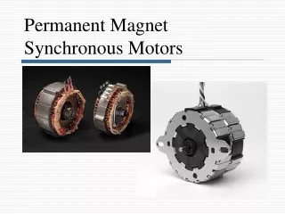
INTRODUCTION • BESS (Battery Energy storage System) is used for load compensation of PMSG driven by diesel engine to enhance its performance. • BESS has capabilities of reactive power, harmonics, unbalanced load compensation. • Control of BESS is achieved by indirect current control scheme. • The voltage at PCC is controlled using BESS under various loads.
NEED OF BESS • Diesel engine based electricity generation unit (DG set) may be loaded with unbalanced & non-linear loads. • Unbalanced & distorted currents lead to unbalanced & distorted 3 phase voltages at PCC. • It leads to increased fuel consumption, poor efficiency & reduced life of DG sets. • It leads to operation of DG sets under derated condition, results into increased cost of the system.
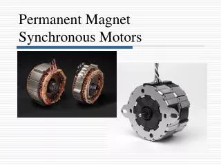
contd.. • The BESS system may improve the performance of DG set to feed unbalanced load without derating. • BESS can provide compensation of harmonics & reactive power & load balancing. • PMSG are most efficient machines & robust due to brushless construction. • Integration of BESS with such a DG set provides active power conditioning . • BESS can absorb excessive power when load is less & can replenish at the time of peak load.
Schematic Diagram for BESS based Supply system BESS-PMSG based DG set feeding to variety of loads:
SYSTEM DESCRIPTION • Consists of the IGBT based 3-phase 3-leg VSI system. • BESS regulates the PCC voltage constant. Hence, voltage regulator is avoided. • The governor block is disabled since the active power drawn from PMSG is kept constant. • This leads to single point of operation & load leveling with BESS.
contd.. • PMSG is operated at constant rated power with proper utilization of generated electrical energy. • The surplus power is absorbed by the BESS and during peak load,it replenishes the increased requirement of load, which offers load leveling. • Here, active component of source current remains fixed, whereas reactive power component depends upon requirement of AC terminal voltage control.
Control Scheme of BESS-PMSG system 11121314
Principle of Operation & Control • 3 phase ism* have two components: • The in-phase component • The quadrature component -(w. r. to phase voltages) • The in phase components of ref. source currents (isad*, isbd*, iscd*) is required to charge battery of BESS and (or) to feed active power to the load. • This active power component may be kept constant. • The magnitudes of ismd* can be assigned to a constant value.
MODELING of Control Scheme • Mainly used to derive ism*,which are used in PWM current controller. • The two components of ism* are estimated as follows: • The in-phase unit vectors, ua = va / Vm; ub = vb / Vm; uc=vc/Vm Vm = 2/3 √(va2+vb2+vc2) va, vb, and vc are the instantaneous voltages at PCC
Contd.. • va = vsan - Rs isa - Ls pisa vb = vsbn - Rs isb - Ls pisb vc = vscn - Rs isc - Ls pisc vsan, vsbn, and vscn are the three phase instantaneous input supply voltages at PCC • vsan=vsm sin(ωt) vsbn=vsm sin(ωt-2π/3) vscn=vsm sin(ωt+2π/3) • The in-quadrature unit vectors can be derived by taking a quadrature transformation of the in-phase unit vectors ua, ub and uc as:
Contd.. • wa = - ub/ √3 + uc/ √3 wb = √3 ua/ 2 + (ub -uc)/(2 √3) wa = -√3 ua/ 2 + (ub -uc)/(2 √3) • The quadrature component of the reference source currents is computed as: • Ver(n) = Vref(n) – Vm(n) • I*smq(n) = I*smq(n-1) +K p { Ver(n) - Ver(n-1) }+ KiVer(n) • i*saq = I*smq wa; i*sbq = I*smq wb; I*scq = I*smq wc
Contd.. • The in-phase component of the reference source currents is computed as: i*sad = I*smd ua; i*sbd = I*smd ub; i*scd = I*smd uc • Reference source currents are computed as: • i*sa=i*saq+i*sad; i*sb= i*sbq + i*sbd; i*sc= i*scq + i*scd
Modeling of Permanent Magnet Synchronous Machine where, φ d = Ld id + Lmd ( i’fd + i’kd) φ q = Lq iq + Lmq i’kq φ’fd = L’fd i’fd + Lmd ( id + i’kd) φ’kd = L’kd i’kd + Lmd ( id + i’fd) φ’kq2= L’kq2i’kq2+Lmqiq • Vd =Rsid+p φ d-wr φ q • Vq = Rsiq + p φ q + wr φ d • V’fd = R’fdi’fd + p φ’fd • V’kd = R’kdi’kd + p φ’kd • V’kq1=R’kq1i’kq1+p φ’kq1 • V’kq2 = R’kq2i’kq2 + p φ’kq2
Modeling of System Loads • Balanced and Unbalanced Delta Connected Linear Loads The current derivative model equations are given as: p iLap = (vab - RLiLap )/ LL p iLbp = (vbc - RLiLbp )/ LL p iLcp = (vca - RLiLcp )/ LL In case of unbalanced loads the particular phase of the load is made open.
Contd.. 2. Non-Linear Load The basic equations in derivative form are as: p id = (vmax-vd )/ 2 Ls p vd = (id- io)/ Co
Contd.. 3. The Motor Load • The model equations defining transient performance of an induction machine are represented as: [v] = [R] [i] +[L] p[i] + wr [G] [i] Te = J(2/poles) p wr + TL where [ v ] = [vsd vsq vrd vrq ]T [ i ] = [isd isq ird irq ]T Te = (3/4) poles Lm (isq ird – isd irq) • p[i] = [L]-1 {[v] – [R] [i] – wr [G] [i]} pwr = poles (Te – TL) / (2 J) For generating mode load torque is made negative.
Advantages of BESS-PMSG system • The system can feed unbalanced loads without derating. • Can provide compensation for harmonics and reactive power and load balancing. • It provides active power conditioning featuring power quality improvement. • It avoids the need of voltage regulators. • It offers load leveling.
SUMMARY • The BESS can be used to improve the performance of a diesel driven PMSG. It regulates supply currents under unbalanced load currents. • The control scheme & modeling of BESS-PMSG system is discussed.
REFERENCES [1] Jashvir Singh, Rajveer Mittal, D. K. Jain, ”Improved Performance of Diesel Driven Permanent Magnet Synchronous Generator Using Battery Energy Storage System”, IEEE Electrical Power & Energy Conference 2009 [2] M.D. Anderson, D. S. Carr, ”Battery Storage Technologies”,Voltage.81,No.3,pp 475-479, March 1993 [3]www.wikipedia.org
Technical Presentations, Research Reviews, New designs & Developments Log On to www.technologyfuturae.com TechnologyFuturae