Download
1 / 33
330 likes | 341 Vues
Learn about the modern RF design process, predictive design methodology, and practical design tips based on real case studies. Introduce new engineers to RF design and measurement techniques.

E N D
HP RF Design and Measurement Seminar Creators: David Ballo Andy Potter Boyd Shaw My Le Truong Joe Civello Ed Henicle Sara Meszaros
Goals of the Seminar • Introduce new engineers to the modern RF design process • Document predictive RF design process • Focus on design methodology, not button pushing • Provide practical design tips based on our case study
Agenda • Introduction • Overview of RF Design Process • Case Study: RF Front-End • Low-Noise Amplifier (LNA) • Duplexer • Power Amplifier • Measurement for Design • Passive Device Characterization • Active Device Modeling • Summary
Traditional RF Design Process • Paper, pencil, calculator • Many board turns (cut and try) • Long design cycles
Modern, Predictive RF Design Process • Combination of: • EDA (electronic design automation) software • Measurement equipment (e.g., network & signal analyzers) • Design iterations now performed via software • Fewer board turns (faster time to market) • Accurate circuit performance - minimize over engineering • Improve manufacturability with yield analysis and optimization
Agenda • Introduction • Overview of RF Design Process • Case Study: RF Front-End • Low-Noise Amplifier (LNA) • Duplexer • Power Amplifier • Measurement for Design • Passive Device Characterization • Active Device Modeling • Summary
Three Critical Design Considerations Time to Market Performance Cost
General RF Design Process Concept Design Integration
Concept:System Design\Analysis\Partition • Assess goals • Set priorities • Explore possible system configurations • Design partitioning • Allocate circuit specifications
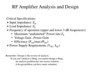
Id h Vds w Circuit Level Design • Explore possible circuit topologies • Investigate and select components • Make build vs. buy decisions • Determine whether desired circuit Specifications are realizable • Verify system performance
Integration • Combine individual circuits • Troubleshoot • System redesign, as needed • Circuit redesign • Circuit reallocation • System reconfiguration • Modify system specification, as needed • Re-define project definition, as needed
Concept:System Design/Analysis/Partition • Understand needs and goals • Paper study • Prone to errors • Incomplete system analysis • Difficult to analyze circuit interactions
Circuit Level Design • Reliance on physical breadboards (prototypes) • Trial-and-error circuit design (cut & try) • Difficult to verify circuit's performance on system level • Difficult to predict interactions & manufacturing yield • Expensive & time consuming!!!
circuits system Once integrated, system = circuit + circuit interactions interactions Integration & Test • Trouble shooting • System level • Circuit level • Little flexibility • Expensive changes • Inefficient process spurs! oscillation! I didn't see any of this coming! When do I go home?
Traditional Design Process Design Concept Integrate Redesign Design Build Integrate Test Does it work? Production NO Production
Concept Design Integration Modern, Predictive RF Design Process • Combine test equipment and EDA software for fast, efficient design! Concept Design Integration
Investment in Models • Dedicate modeling team • Use available parts libraries • Measure individual parts • Different operating conditions • Improve individual parts models with time Ibe=(IBbif(exp(Vbe/NbfVT)-1.0))+Ise(exp(Vbe/(NexVt))-1.0) !Freq.[Hz] MagS11[dB] PhaseS11[DEG] MagS21[dB] PhaseS21[DEG] MagS12[dB] PhaseS12[DEG] 300000 -5.986E-07 -1.151E-02 -7.394E+01 8.997E+01 -7.394E+01 8.997E+01 -5.986E-07 -1.151E-02 315229 -6.384E-07 -1.210E-02 -7.351E+01 8.997E+01 -7.351E+01 8.997E+01 -6.384E-07 -1.210E-02 331231 -6.812E-07 -1.271E-02 -7.308E+01 8.997E+01 -7.308E+01 8.997E+01 -6.812E-07 -1.271E-02 348046 -7.273E-07 -1.336E-02 -7.265E+01 8.997E+01 -7.265E+01 8.997E+01 -7.273E-07 -1.336E-02 365714 -7.769E-07 -1.403E-02 -7.222E+01 8.997E+01 -7.222E+01 8.997E+01 -7.769E-07 -1.403E-02 384279 -8.303E-07 -1.475E-02 -7.179E+01 8.997E+01 -7.179E+01 8.997E+01 -8.303E-07 -1.475E-02 403787 -8.879E-07 -1.550E-02 -7.136E+01 8.997E+01 -7.136E+01 8.997E+01 -8.879E-07 -1.550E-02 424285 -9.501E-07 -1.628E-02 -7.093E+01 8.997E+01 -7.093E+01 8.997E+01 -9.501E-07 -1.628E-02 445823 -1.017E-06 -1.711E-02 -7.050E+01 8.997E+01 -7.050E+01 8.997E+01 -1.017E-06 -1.711E-02 468455 -1.090E-06 -1.798E-02 -7.007E+01 8.997E+01 -7.007E+01 8.997E+01 -1.090E-06 -1.798E-02 492235 -1.168E-06 -1.889E-02 -6.964E+01 8.997E+01 -6.964E+01 8.997E+01 -1.168E-06 -1.889E-02 517223 -1.252E-06 -1.985E-02 -6.921E+01 8.997E+01 -6.921E+01 8.997E+01 -1.252E-06 -1.985E-02 543479 -1.344E-06 -2.086E-02 -6.878E+01 8.997E+01 -6.878E+01 8.997E+01 -1.344E-06 -2.086E-02
Quickly and accurately analyze system performance ! Concept: System Design/Analysis/Partition circuits system • Top-level system brainstorming • Quick analysis ofcircuit interactions • Budget analysis to allocate circuit specifications • Design partitioning system-level interactions
Classic Example: Spur Analysis • Select frequency plan based on predicted performance
Receiver Block D/A I AGC A/D Baseband DSP Frequency Synthesizer 90 A/D Q From Synthesizer Circuit Envelope Simulation Transient Simulation HP Ptolemy Simulation Integrated Design Environment To D/A
Design Modify design to match proto Simulate (Circuit & System) Good Build physical proto & test Good Integrate Circuit Design Cycle
Circuit DesignBrainstorm • Experiment with possible biasing schemes • Explore different circuit configurations • Make many different analyses quickly
Continuing to optimize with- out a physical Careful! Proceed with caution. prototype Why Modify Design to Match Prototype? First, verify that there are no errors in the fabrication or measurement of the prototype. Why modify the design to match the prototype? Provides starting point to refine design Gives good assurance that design changes will indeed improve design direction! The closer prototype matches the model, the greater the probability for success : right c Ps =(k) x 100 where Ps= success probability c = # of changes k = guru factor (<1.0)
s21 log mag 10dB/div 0dB ref simulated measured 2 Integration: Layout & Prototype • Interconnect designs and measure performance • Modify design to reflect measured results (if necessary)
Measured System Modeled System Production Success! Measured = Modeled & Exceeds Spec
Design Integrate Software Simulate Redesign Does it work? NO Manufacturable? NO Build Test NO Does it work? Physical Production The Predictive RF Design Process Concept • Tweak the design on the work station, not on the bench! Design Integrate Production
HP Advanced Design System Total integration of schematic, simulation, and layout
The RF Design Process Concept Design Production Integration & Test • System Analysis • Design Partitioning • RF • Analog • DSP • Integrate Blocks • System Measurements • Re-Layout • Final Artwork • Bill of Materials • Documentation • Integrated Simulators • Faster Simulators • Optimizers • Instrument I/O • Parts Libraries • Co-Simulation • System Simulation • Layout • EM Simulation • Parts Libraries • Third Party Links • Artwork Generation
HP’s Measurement Instrumentation • HP Advanced Design System • Network and Signal Analyzers • Protocol Signal Sources (CDMA, GSM, etc.)