RF structure design
RF structure design. KT high-gradient medical project kick-off 30.05.2013 Alberto Degiovanni TERA Foundation - EPFL. Outline. Introduction RF cavities constraints for hadrontherapy Backward travelling wave cell design and optimization for high gradient operations Nose cone study

RF structure design
E N D
Presentation Transcript
RF structure design KT high-gradient medical project kick-off 30.05.2013 Alberto Degiovanni TERA Foundation - EPFL
Outline • Introduction • RF cavities constraints for hadrontherapy • Backward travelling wave cell design and optimization for high gradient operations • Nose cone study • Tapering • Comparison of different structure designs • SW SCL design • backward TW • Preliminary studies for linac design • Conclusions A. Degiovanni
Linac layout and BDR requirements • Quasi-periodic PMQ FODO lattice sets a limit to the length of each structure and determines the group velocity range. • The cells in each structure (tank) have the same length, while from one tank to the next, the cell length increases: β tapering in the range 0.22-0.60 • Trade-off between transverse acceptance and RF efficiency: bore aperture = 5 mm • Max BDR: 1 BD per treatment session (~ 5 min) on the whole linac length (~ 10 m). BDR ~ 10-6 bpp/m ... A. Degiovanni
Novel design for high gradient operation A. Degiovanni
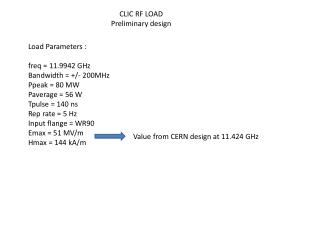
Proposal for bTW design for hadrontherapy P_wall DESIGN GOAL and CONSTRAINTS Ea:= E0T ≥ 50 MV/m Sc/Ea2 < 7 10-4 A/V L P_0 P_load z with: Sc< 4 MW/mm2 tTERA = 2500 ns • tCLIC = 200 ns • BDRTERA = BDRCLIC = 10-6 bpp/m Proposed by A. Grudiev vg_in ~ 0.4% c vg_out ~ 0.2% c fillingtime ~ 0.3 µs A. Degiovanni
8 holes (22.5 deg sweep) – radius scan vg [10-3 c] ~ (r[mm])3.65 ROI group velocity ROI nose_Sc/Ea^2 normalizedSc in the couplinghole [10-4Ω-1] doubling the number of holes will double vg while keeping Sc_hole almost constant
Nose geometry optimization half gap • Scan on: • Nose cone angle • Gap • Nose cone radius(*) • Phase advance (120°-150°) • coupling hole radius (vg = 4 ‰ and 2 ‰ ) • Optima: • Minimum of the quantity: noseradii nose angle septum bore radius * based also on results of the SCL optimization A. Degiovanni
angle scan – 120 deg g5 a25 g5 a75 g5 a55 A. Degiovanni
Optimization plots R’/Q [Ω/m] R’ (or ZTT) [MΩ/m]
Optimization plots vg [10-3 c] R’/Q [Ω/m] Sc/Ea2 [10-3Ω-1]
Optimization plot – 120 deg – gap = 5.5 mm min {Max {Xnose,Xslot}}
gap and angle scan – 120 deg g4 a55 g4 a75 g4 a25 g5 a25 g5 a75 g5 a55 g6 a25 g6 a75 g6 a55
120° - 16 holes – nose 1 -2 mm – gap and angle scan g 5.5 mm A 65 deg g 5.5 mm A 65 deg
120° - 16 holes – nose 1 -2 mm – gap and angle scan g 5.5 mm A 65 deg g 5.5 mm A 65 deg
150° - 16 holes – nose 1 -2 mm – gap and angle scan g 7.0 mm A 55 deg g 7.0 mm A 55 deg
150° - 16 holes – nose 1 -2 mm – gap and angle scan g 7.0 mm A 55 deg g 7.0 mm A 55 deg
COMPARISON between TW and SW structures A. Degiovanni
Comparison between TW structure and SCL Tapered structures: the coupling holes are smaller along the structure PUT NEW PLOT Geometry of LIBO structure A. Degiovanni
Comparison of E-field in TW and SW π/2 phase advance 2/3 π phase advance A. Degiovanni
waveguide accelerating cavities coupling cavities PROs and CONs of bTW compared to standard SCL design I. Syratchev A. Degiovanni
Preliminary design for high gradient bTW linac ~15-16 MW klystron 2 x 7.5 MW klystrons 1 3 3 load load load load 2 2 T1 T1 T2 T2 MKs MKs Independent rotary joints -3 dB recirculation Small RF load compared to TW A. Degiovanni
Global optimization of bTWlinac Gain ~ 1.8 • Energy range: 60-230 MeV • 16 structures (tanks) – Total length: 5.9 m • 16x7.5 MW klystrons – 8 modulators • Total peak power needed: 206 MW • Peak power with recirculators: 114 MW • Effective filling time increases to 2.1-3 μs • Total average power from MKs: 150 kW • Energy range: 65-230 MeV • 16 structures (tanks) – Total length: 5.5 m • 16x7.5 MW klystrons – 8 modulators • Total peak power needed: 260 MW • Peak power with recirculators: 120 MW • Effective filling time increases to 1.8-2.5 μs • Total average power from MKs: 150 kW Gain ~ 2.2 A. Degiovanni
Fast active energy and intensity modulation:RF pulses and beam pulses 5.0 μs Klystron RF pulse P 8 ms Active energy modulation 2.5 μs P RF power into the tanks I Proton pulses from source Active intensity modulation time A. Degiovanni
Summary • Optimization of TW structures for high gradient operations has been performed for 120° and 150° phase advance. • The RF design of the input and output coupler is now ongoing. • The optimization of the whole linac layout has started recently and needs some iterations, but looks promising • The design and test of the novel bTW structures is boosting the TULIP project! A. Degiovanni
TULIP-CLIC-bTW – beta=0.3798 (W=76 MeV) Circular coupling holes Racetrack slot position DIAM/2 angle R_coupling Rc Rectangular slot csl_h GAP/2 Rcorner position angle LENGTH R_coupling A. Degiovanni