RF System Design Review for IB1 VTS: Committee Overview and Project Insights
90 likes | 248 Vues
The RF System Design Review committee, chaired by Ralph Pasquinelli, includes members Brian Chase, Wolf-Dietrich Moeller, John Reid, Jim Steimel, and Chuck Worel. The committee's charge is to assess the technical aspects of the IB1 Vertical Test Stand RF system design and provide a comprehensive written report. The review outlines the project's framework, including requirements, block diagrams, components, and implementation strategies. Key measures involve testing SRF cavities, ensuring cryogenic capacities, and planning for future horizontal test facilities while maintaining controlled area status.

RF System Design Review for IB1 VTS: Committee Overview and Project Insights
E N D
Presentation Transcript
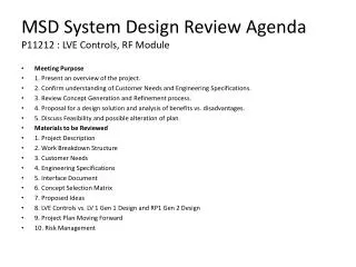
RF System Design Review • Welcome committee members • Brian Chase • Wolf-Dietrich Moeller • Ralph Pasquinelli (chair) • John Reid • Jim Steimel • Chuck Worel • Charge to the committee • Assess and comment on all technical aspects of the IB1 VTS RF system design, and • Provide a written report. VTS RF Design Review
Outline of the RF Design Review • Intro to the Vertical Test Stand project (CMG) • VTS RF System Project (Joe) • RF System Design • Requirements • Block diagram • Specific components • RF System Implementation • Tasks, milestones, resources • Status and plans VTS RF Design Review
IB1 VTS Overview • Test bare 1.3 GHz 9-cell SRF cavities • Measure Q vs. T • Measure Q vs. Eacc at 2K • Cryo capacity ~125 W at 2K • 250 W (CW) RF power required (Q>5x10⁹, Eacc<35 MV/m) • Maintain “Controlled Area” status in IB1 VTS RF Design Review
Location • West side of IB1, North of the Vertical Magnet Test Facility (VMTF) • Allows for the future construction a horizontal test cryostat (or something else) • Is in close proximity to the existing VMTF Cryogenic piping; may simplify the tie-in to the cryogenic services Vert. SRF Cryostat Cryo Piping VTS RF Design Review
Location (cont.) Long-term plan for IB1 is to have both a vertical facility and a horizontal test facility (or something else) Radiation Shielding VMTF Vertical SRF IB1 Control Rm. VTS RF Design Review
Civil Construction Complete (August 2) labyrinthine instrumentation trench recessed area vertical pit East North VTS RF Design Review
Radiation Shielding • Shielding design complete • Design from MARS15 simulation (I. Rakhno) • approved by ES&H • available as Fermilab-TM-2350-AD • Design consists of pit walls, internal shielding plug, and movable lid • Movable radiation shielding lid part of personnel safety interlock system VTS RF Design Review
VTS Project Schedule We are here • Schedule is driven by cryostat fabrication/installation • PSS interlock conceptual design before RF Design complete VTS RF Design Review