Download
1 / 26
260 likes | 276 Vues
This article discusses the electron cloud effect in accelerators and its impact on beam instabilities, emittance increase, and lower luminosity. It presents the work performed by Mauro Pivi at SLAC and the ILC Damping Ring Working Group.

E N D
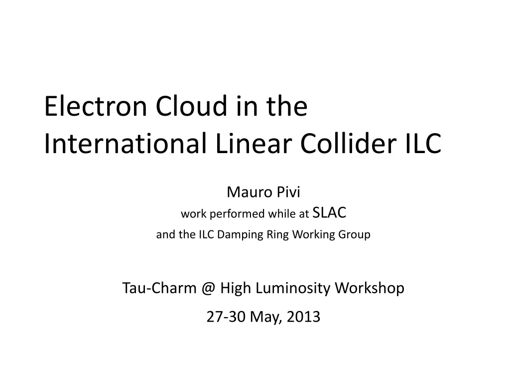
Electron Cloud in the International Linear Collider ILC Mauro Piviwork performed while atSLAC and the ILC Damping Ring Working Group Tau-Charm @ High Luminosity Workshop 27-30 May, 2013
Electron Cloud in a nutshell • In the vacuum chambers of an accelerator, electrons are generated by photons, ionization, etc. • e- are accelerated by the passing bunches, hit the chamber and multiply due to surface Secondary Electron Yield (SEY) • After few bunches pass, a cloud of electrons may form • The cloud couples with the beam to cause beam instabilities and emittance increase, beam losses and lower luminosity • The electron cloud has been observed in several machines as PEP-II, KEKB, LHC, Daphne, CesrTA, and others • It is a Very High Priority Issue for the ILC, CLIC, SuperKEKB, SuperB with ultra-low emittance
The Luminosity Challenge: Electron Cloud Effect In a positron or proton storage ring, electrons are generated by a variety of processes, and can be accelerated by the beam to hit the vacuum chamber with sufficient energy to generate multiple “secondary” electrons. Under the right conditions, the electron “cloud” density can reach high levels and can drive the beam unstable and increase the beam size decreasing the collider luminosity. Electron cloud in the LHC 25 ns 25 ns
Electron cloud in the Linear Colliders • While at SLAC, coordinating the ILC electron cloud Working Group (WG) • WG milestones: development of mitigations for the electron cloud that lead to reduction of Damping Rings circumference from 17km to 6km (2006) and then to 3km (2010) Latest years goal: • Develop mitigations and give recommendation for the ILC Tau-Charm @ high L
Recommendation of Electron Cloud Mitigations amorphous-Carbon SLAC Grooves on Cu Grooves w/TiN coating Manufacturing Techniques& Quality CERN CesrTA Reliable Feedthroughs KEK Clearing Electrode CESRTA Stable Structures INFN Frascati Clearing Electrodes KEKB
Electron Cloud Mitigations Evaluation Criteria • The Working Group (about 50) met at a dedicated Workshop to evaluate technologies and give recommendation on electron cloud mitigations Efficacy • Photoelectric yield (PEY) • Secondary emission yield (SEY) • Ability to keep the vertical emittance growth below 10% Cost • Design and manufacturing of mitigation • Maintenance of mitigation • Ex: Replacement of clearing electrode PS • Operational • Ex: Time incurred for replacement of damaged clearing electrode PS Risk • Mitigation manufacturing challenges: • Ex: ≤1mm or less in small aperture VC • Ex: Clearing electrode in limited space or in presence of BPM buttons • Technical uncertainty • Incomplete evidence of efficacy • Incomplete experimental studies • Reliability • Durability of mitigation • Ex: Damage of clearing electrode feed-through Impact on Machine Performance • Impact on vacuum performance • Ex:NEG pumping can have a positive effect • Ex: Vacuum outgassing • Impact on machine impedance • Ex: Impedance of grooves and electrodes • Impact on optics • Ex: x-y coupling due to solenoids • Operational • Ex: NEG re-activation after saturation Tau-Charm @ high L
Structured Evaluation of EC Mitigations Tau-Charm @ high L
Summary of Electron Cloud Mitigation Plan for the ILC Baseline Mitigation Recommendation - EC Workshop, Cornell University • Aggressive mitigation plan needed to obtain optimum performance for 3.2km positron damping ring and to pursue the high current option M. Pivi, S. Guiducci, M. Palmer, J. Urakawa on behalf of the ILC DR Electron Cloud Working Group Tau-Charm @ high L
Mitigations: Wiggler Chamber with Clearing Electrode • Thermal spray tungsten electrode and Alumina insulator • 0.2mm thick layers • 20mm wide electrode in wiggler • Antechamber full height is 20mm ILC Wiggler chamber Joe Conway – Cornell U.
Mitigations: Dipole Chamber with Grooves • 20 grooves (19 tips) • 0.079in (2mm) deep with 0.003in tip radius • 0.035in tip to tip spacing • Top and bottom of chamber ILC Dipole chamber Joe Conway – Cornell U.
Electron cloud assessment in the ILC Damping Ring for 2013 TDR report WG latest years goal: • Estimate the electron cloud effect by simulations including full mitigation plan • For the ILC Technical Design Report (TDR) 2013
Electron cloud assessment: 3-step Simulation plan 2. Evaluate electron cloud build-up in BENDs with grooves - LBNL 1. Map the photoelectron distribution 3. Evaluate beam Instability Photon generation and distribution by Cornell U. In WIGGLERS with clearing electrodes - SLAC Beam move freely interacting with cloud - SLAC map map In DRIFT, QUAD, SEXT with TiN coating - Cornell U.
Photon rates, by magnet type and regiondtc03 Photon azimuthal distributions in various chamber types G. Dugan Cornell U. Used Synrad3d a 3D simulation code that includes the ring lattice at input and full chambers geometry (3D photon tracking, photon stops, antechambers, reflectivity, etc.)
Evaluation results: Electron Cloud in Drift Regions, with Solenoid field (40 G) • Solenoid fields in drift regions are very effective at eliminating the central cloud density Chamber-average cloud density Near-beam cloud density J. Crittenden, Cornell U.
Electron Cloud in Quadrupoles • Trapping of electron in quadrupole field: the electron cloud density does not reach equilibrium after 8 bunch trains. J. Crittenden, Cornell U.
Electron Cloud in Quadrupoles Electron cloud density (e/m3) Electron energies (eV) J. Crittenden, Cornell U.
Electron Cloud in arc Sextupoles Electron cloud density (e/m3) Electron energies (eV) J. Crittenden, Cornell U.
Wiggler Magnets: Clearing Electrodes Modeling of clearing electrode: round chamber is used Clearing Field (left) & potential (right) L. Wang, SLAC
Wiggler magnets: Effect of Clearing Electrodes on Electron Cloud Distribution 0V +100V +600V +400V +600V L. Wang, SLAC
Summary of Electron Cloud distribution along the ILC DR with mitigations implemented Simulation with full lattice • This expected cloud density is already promisingly low. • Next step is to compute if this cloud density destabilizes the beam.
Last step: evaluate beam instability • Used C-MAD parallel code (M. Pivi while at SLAC et al.): electron cloud instability, Intra-Beam Scattering IBS. Allows uploading the full SPS lattice from MAD for increased realistic simulations. • Simulations challenge: very flat beams in ILC DR
Calculation of emittance growth and beam instability Upload full MAD lattice place electron clouds along ring with varying the cloud density Track beam Though, below the instability threshold, there is a persistent linear emittance increase There is a clear threshold to exponential growth between 3÷5 e11 e/m3cloud density.
Estimated Vertical emittance growth with full lattice Result: Vertical emittance growth with full lattice Expected average cloud density with mitigations is 3.5e10 e/m3 The fractional emittancegrowth in 300 turns = 0.0016 Beam Store time in ILC DR =18550 turns Thus estimated emittance growth in 18550 turns ~ 10% 10% emittance growth is acceptable, Mitigations are effective in the ILC DR! 3.5e10 e/m3
Summary of Electron cloud in the ILC • During last years, developed novel mitigations in a multi-laboratory collaborative effort • Recommended mitigations for each DR region • Intensely developed simulation codes • Methodically evaluated electron cloud effect • With mitigations, the electron cloud density is well below the instability threshold • A persistent slow emittancegrowth due to electron cloud is an acceptable 10% • Mitigations are effective in DR
SuperB: Buildup in the arcs Dipoles HER Arc quadrupole vacuum chamber (CDR) By=0.3 T; =99% SEY=1.0SEY=1.1SEY=1.2SEY=1.3 Snapshot of the electron (x,y) distribution “just before” the passage of the last bunch Theo Demma ECLOUD12 Workshop
SuperB: Summaryfrom talk at Electron Cloud Workshop 2012 Challenging! • Simulations indicate that a peak secondary electron yield of 1.1 and 99% antechamber protection result in a cloud density below the instability threshold. • Planned use of coatings (TiN, ?) and solenoids in SuperB free field regions can help. • Ongoing studies on mitigation techniques (grooves in the chamber walls, clearing electrodes) offers the opportunity to plan activity for SuperB. Theo Demma ECLOUD12 Workshop