Download
1 / 23
540 likes | 1.17k Vues
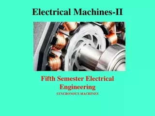
Electrical Machines-II. Fifth Semester Electrical Engineering SYNCRONOUS MACHINES. Principle of Operation.

E N D
Electrical Machines-II Fifth Semester Electrical Engineering SYNCRONOUS MACHINES
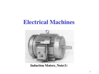
Principle of Operation • The operation of a synchronous generator is based on Faraday's law of electromagnetic induction, and in an ac synchronous generator the generation of emf's is by relative motion of conductors and magnetic flux. • These machines can be used as either motors or generators but their predominant use is in generation. • There are a number of sources of energy used to turn the turbines:- • (a) Gas (b) Steam(c) Combined cycle (d) Nuclear(e) Hydro (f) Wind(g) Wave (h) Photovoltaic
Principle of Operation Multiple Pole Rotor
Principle of Operation • In constructing a synchronous machine a point to note is that the stator is fixed and the poles rotate. • There are two categories of Synchronous machines: • (a) those with salient or projecting poles • (b) those with cylindrical rotors A Cylindrical Rotor 2-pole Cylindrical Rotor
Principle of Operation 4-Pole Salient Rotor A Salient Pole Rotor
Principle of Operation Its characteristic feature is that the armature rotates through a stationary magnetic field, and the generated AC is brought to the load by means of slip rings and brushes. The revolving-armature alternator is found only in alternators of small power rating and is not generally used. This is because a rotating armature requires slip rings and brushes to conduct the current from the armature to the load.
Principle of Operation The revolving-field type alternator has a stationary armature and a rotating magnetic field. The generated voltage can be connected directly to the load without having to pass across the slip rings and brushes. The voltage applied to generate the rotating field is a small DC voltage (called a “field excitation” voltage)
Winding factor is the product of pitch factor and distribution factor
Armature reaction at unity, lag and lead power factor • At unity power factor, the angle between armature current I and induced emf E, is zero • The armature reaction is cross magnetising when the generator supplies a load at unity power factor. • At lagging zero electrical power factor, the armature current lags by 90o to induced emf in the armature • At leading power factor condition, armature current "I" leads induced emf E by an angle 90o • When the generator supplies a load at leading power factor the armature reaction is partly demagnetising and partly cross-magnetising.
OPEN CIRCUIT CHARACTERISTICS If not for the magnetic saturation of the iron, the open circuit characteristics would be linear as represented by the air gap line
SHORT CIRCUIT CHARACTERISTICS On short-circuit the machine runs at it synchronous speed (n = ns) and IL = IFL For s/c Vt = 0, Therefore E / IL = Zs and Isc = IL = E / Zs In conventional synchronous machines the short circuit characteristics is practically linear because the iron is unsaturated up to rated armature current
Generator power flow=> out Motor power flow=> in Power flow out of a Synchronous Machine
Power flow out of a Synchronous Machine • = Load angles In practical synchronous machines, except for small ones, Xs >> Ra so we could assume that Zs = jXs in the analysis. Therefore we get E = Vt + jILXs
Power flow out of a Synchronous Machine Power = VIcosf Considering the diagram h = ILXscosf = Esind Therefore ILXscosf = Esind
Power flow out of a Synchronous Machine For maximum power sind = 1Therefore d = 90 In which case
Hunting and prevention • Rotor swings or oscillates about new equilibrium position. This phenomenon is known as hunting or phase swinging. Causes of Hunting in Synchronous Motor • Sudden change in load • Sudden change in field current • A load containing harmonic torque. • Fault in supply system Effects of Hunting in Synchronous Motor • loss of synchronism. • Produces mechanical stresses in the rotor shaft. • Increases machine losses and cause temperature rise. • Cause greater surges in current and power flow
Reduction of Hunting in Synchronous Motor • Use of Damper Winding: It consists of low electrical resistance copper / aluminum brush embedded in slots of pole faces in salient pole machine. Damper winding damps out hunting by producing torque opposite to slip of rotor. The magnitude of damping torque is proportional to the slip speed. • Use of Flywheels: The prime mover is provided with a large and heavy flywheel. This increases the inertia of prime mover and helps in maintaining the rotor speed constant.
Applications • Synchronous motors are used to regulate the voltage at the end of transmission lines • They can be employed for loads which require constant speeds • These motors used for power factor correction applications can also be termed as "synchronous condensers • Synchronous motors are used in generating stations and in substations connected to the bus bars to improve the power factor