Download
1 / 49
580 likes | 1.17k Vues
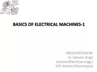
BASICS OF ELECTRICAL MACHINES-1. PRESENTATION BY: Er. Satnam Singh Lecturer(Electrical engg.) GPC Mohali (Khunimajra). Contents. Overview of Electrical Machines Construction Principle of Operation Types of DC Generator Types of DC Motor. LEARNING OBJECTIVES .

E N D
BASICS OF ELECTRICAL MACHINES-1 PRESENTATION BY: Er. Satnam Singh Lecturer(Electrical engg.) GPC Mohali (Khunimajra)
Contents • Overview of Electrical Machines • Construction • Principle of Operation • Types of DC Generator • Types of DC Motor
LEARNING OBJECTIVES • Upon completion of this chapter the student should be able to: • State the principle by which machines convert mechanical energy to electrical energy. • Discuss the operating differences between different types of generators and motor. • Understand the principle of dc generator and dc motors.
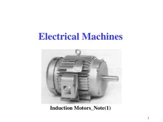
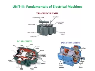
Overview of Electrical Machines • A machine is an electromechanical energy conversion device which converts the form of energy i.e. from mechanical to electrical or from electrical to mechanical energy • Depending upon the working of the machine ,the electromechanical energy conversion device may be named as generator or motor.
Generator • A generator is a machine that converts mechanical energy into electrical energy by using the principle of magnetic induction. Principle of magnetic induction in DC machine
GENERATOR ACTION • Figure show an elementary coil rotating in a stationary magnetic field between a pair of magnetic poles. • Let it rotated in anticlockwise direction at an angular velocity of ω radian per sec, by some prime-mover giving the generator a mechanical torque Tm
WORKING PRINCIPLE OF A DC GENERATOR • The coil side or conductors cut the magnetic lines of force and hence an emf is induced in the coil.(Faradays law) • The coil is further connected to an external resistance R , therefore current ‘i’ flow through the coil side as well as through the load resistance R • The direction of current the current is marked on the coil sides. • Now the second action start ,i.e. a current carrying coil or conductor is placed in the magnetic field and hence the conductor will experience a force or torque Te the direction of torque will be opposing to the driving torque Tm • Tm = Te + Tf • ωTm = ωTe + ωTf • where ωTm = mechanical input power • ωTe = mechanical power available for conversion into electrical power • ωTf = mechanical power lost due to friction
FARADAYS LAW OF ELECTRO-MAGNETIC INDUCTION • When a conductor cut across the magnetic field, an e.m.f. is induced in the conductor • When the magnetic flux linking with any circuit or coil changes an e.m.f. is induced in the circuit • Observes • The deflection in the galvanometer needle shows that e.m.f. is induced in the coil. • The direction of induced e.m.f. in the coil depend upon the direction of magnetic field and the direction of motion of coil • E.m.f. induced in the coil only when flux linking with the circuit changes i.e. either magnet or coil is in motion.
Motor • An motor is a machine that converts electrical energy into mechanical energy by supplying a electrical power (voltage and current).
MOTOR ACTION • Fig shows a coil placed in a constant stationary magnetic field. the resistance R is removed and in place of this a battery is connected across the coil. • Now the current ‘i’ will start flowing through the coil. the current carrying conductor produces a magnetic field Fr
The field Fr tries to come in line with the main field Fm. • Thus an electromagnetic torque Te is developed in the coil is anticlockwise direction. therefore coil start rotating in anticlockwise direction say at an angular speed ‘ω’ rad/sec • Now again the second action start, when the coil moves in the magnetic field, flux is cut by the conductors and hence an emf is induced in them. • The direction of this induced emf will be opposing the cause due to which the emf is induced. • Thus the induced emf will be opposing the supply voltage v and the current in the coil will flow due to the difference between v and e. if r is the resistance of the coil. • Then applied voltage V = e + ir • Multiplying both side by ‘i’ in equation we get • Vi = e.i+ i2r • Here Vi = electrical power input to the machine • e.i. = electrical power available for conversion into mechanical power • I2r = power lost due to resistance of the coil.
CONSTRUCTION Main parts of dc machine are: Field magnet frame or yoke Pole cores and pole shoes Pole coil or field coils Armature core Armature winding Commutator Brushes Brush holder Bearing Shaft
FIELD MAGNET FRAME OR YOKE The yoke or outer frame is the covering provided to dc generator and it serves the following purpose It provides a mechanical support for the poles. It act as a protective cover against mechanical damage It provide a passage for the magnetic flux produced by the poles.
POLE CORE AND POLE SHOES • The pole core itself may be made of solid piece of cast iron or cast steel, but pole shoe is laminated and is screwed to the pole face by means of counter sunk screw. • The pole cores may be made of thin laminations of steel, riveted together.This type of pole is held in position with the frame by means of bolts. • The pole shoe serves the two purpose as under. • It support the pole coils. • Being of larger cross section, it spread the flux and also reduces the reluctance of the magnetic path.
ARMATURE • The armature core is cylindrical in shape. It is rotating part of the machine • Its body is made up of soft iron stamping or laminations to reduce the eddy current losses. • The lamination are keyed to the shaft. These are insulated from each other by varnish. • At the outer periphery slots are cut. The armature conductors (winding)are placed in these slots • The armature core serves the following purpose • It provides a path of low reluctance to the magnetic flux. • It house armature conductors DC machine armature
ARMATURE WINDINGS • The armature coil are usually former wound. The conductor are placed in the armature slots which are lined with tough insulating material. • The slot insulation is folded over the armature conductors placed in the slots and is secured firmly by bumboo or fibre wedges. • The armature winding are usually of conductors covered with single cotton cover, double cotton cover or enamalled wire • On the basis of connection these are of two types: • Lap winding • Wave winding
ARMATURE WINDINGS • Lap Wound Armatures • are used in machines designed for low voltage and high current • armatures are constructed with large wire because of high current • Eg: - are used is in the starter motor of almost all automobiles • The windings of a lap wound armature are connected in parallel. This permits the current capacity of each winding to be added and provides a higher operating current • No of current path, C=2p ; p=no of poles Lap wound armatures
ARMATURE WINDINGS (Cont) • Wave Wound Armatures • are used in machines designed for high voltage and low current • their windings connected in series • When the windings are connected in series, the voltage of each winding adds, but the current capacity remains the same • are used is in the small generator • No of current path, C=2 Wave wound armatures
FIELD WINDINGS • Most dc machines use wound electromagnets to provide the magnetic field. • When current passed through these coils, they electromagnetise the poles which produce the necessary flux which is cut by the armature conductors when in motion. • Two types of field windings are used : • series field • shunt field
FIELD WINDINGS (Cont) • Series field windings • are so named because they are connected in series with the armature • are made with relatively few windings turns of very large wire and have a very low resistance • usually found in large horsepower machines wound with square or rectangular wire. The use of square wire permits the windings to be laid closer together, which increases the number of turns that can be wound in a particular space • Square and rectangular wire can also be made physically smaller than round wire and still contain the same surface area Square wire contains more surface than round wire Square wire permits more turns than round wire in the same area
FIELD WINDINGS (Cont) • Shunt field windings • is constructed with relatively many turns of small wire, thus, it has a much higher resistance than the series field. • is intended to be connected in parallel with, or shunt, the armature. • high resistance is used to limit current flow through the field.
FIELD WINDINGS (Cont) • When a DC machine uses both series and shunt fields, each pole piece will contain both windings. • The windings are wound on the pole pieces in such a manner that when current flows through the winding it will produce alternate magnetic polarities. Both series and shunt field windings are contained in each pole piece S – series field F – shunt field
COMMUTATOR • The commutator is cylindrical in structure and is built up of wedge shaped hard drawn copper segments. • The segment are insulated from each other by a thin sheet of high quality mica. • To prevent them from flying out under the action of centrifugal forces, the segments are provided with “v”-grooves, which are insulated by conical mica-nite ring. • The function of the commutator is to facilitate the collection of current from the armature and to rectify the A.C. induced in the armature into D.C.
BRUSH HOLDER AND BRUSHES • The function of brushes is to collect current from the commutator and supply it to the external load circuit. • These are usually made of carbon and are rectangular in shapes. • These brushes are housed in brush holders. • These are held in position under spring tension , the pressure of the spring can be adjusted by altering the position of lever in the notches. • Copper brushes are only used for machine delivering large current at low voltages.
BEARING • These are supported in end cover, because of reliability, ball bearing are usually employed . • Though for heavy duty, roller bearing are employed. • These are used to reduce friction and have less wear and tear.
SHAFT • The material of the shaft is mild steel . It is used to transfer mechanical power from or to the machine. • The rotating parts e.g. Armature, commutator are mounted to the shaft.
Principle operation of Generator • Whenever a conductor is moved within a magnetic field in such a way that the conductor cuts across magnetic lines of flux, voltage is generated in the conductor. • The AMOUNT of voltage generated depends on: • the strength of the magnetic field, • the angle at which the conductor cuts the magnetic field, • the speed at which the conductor is moved, and • the length of the conductor within the magnetic field
Principle of operation (Cont) • The POLARITY of the voltage depends on the direction of the magnetic lines of flux and the direction of movement of the conductor. • To determine the direction of current in a given situation, the LEFT-HAND RULE FOR GENERATORS is used. Left Hand Rules • thumb in the direction the conductor is being moved • forefinger in the direction of magnetic flux (from north to south) • middle finger will then point in the direction of current flow in an • external circuit to which the voltage is applied
THE ELEMENTARY GENERATOR • The simplest elementary generator that can be built is an ac generator. Basic generating principles are most easily explained through the use of the elementary ac generator. For this reason, the ac generator will be discussed first. The dc generator will be discussed later. • An elementary generator consists of a wire loop mounted on the shaft, so that it can be rotated in a stationary magnetic field. This will produce an induced emf in the loop. Sliding contacts (brushes) connect the loop to an external circuit load in order to pick up or use the induced emf. Elementary Generator
THE ELEMENTARY GENERATOR (Cont) • The pole pieces (marked N and S) provide the magnetic field. The pole pieces are shaped and positioned as shown to concentrate the magnetic field as close as possible to the wire loop. • The loop of wire that rotates through the field is called the ARMATURE. The ends of the armature loop are connected to rings called SLIP RINGS. They rotate with the armature. • The brushes, usually made of carbon, with wires attached to them, ride against the rings. The generated voltage appears across these brushes.
THE ELEMENTARY GENERATOR (A) • An end view of the shaft and wire loop is shown. At this particular instant, the loop of wire (the black and white conductors of the loop) is parallel to the magnetic lines of flux, and no cutting action is taking place. Since the lines of flux are not being cut by the loop, no emf is induced in the conductors, and the meter at this position indicates zero. • This position is called the NEUTRAL PLANE. 00 Position (Neutral Plane)
THE ELEMENTARY GENERATOR (B) • The shaft has been turned 900 clockwise, the conductors cut through more and more lines of flux, and voltage is induced in the conductor.at a continually increasing angle , the induced emf in the conductors builds up from zero to a maximum value or peak value. • Observe that from 00 to 900, the black conductor cuts DOWN through the field. At the same time the white conductor cuts UP through the field. The induced emfs in the conductors are series-adding. This means the resultant voltage across the brushes (the terminal voltage) is the sum of the two induced voltages. The meter at position B reads maximum value. 900 Position
THE ELEMENTARY GENERATOR (c) • After another 900 of rotation, the loop has completed 1800 of rotation and is again parallel to the lines of flux. As the loop was turned, the voltage decreased until it again reached zero. • Note that : From 00 to 1800 the conductors of the armature loop have been moving in the same direction through the magnetic field. Therefore, the polarity of the induced voltage has remained the same 1800 Position
THE ELEMENTARY GENERATOR (D) • As the loop continues to turn, the conductors again cut the lines of magnetic flux. • This time, however, the conductor that previously cut through the flux lines of the south magnetic field is cutting the lines of the north magnetic field, and vice-versa. • Since the conductors are cutting the flux lines of opposite magnetic polarity, the polarity of the induced voltage reverses. After 270' of rotation, the loop has rotated to the position shown, and the maximum terminal voltage will be the same as it was from A to C except that the polarity is reversed. 2700 Position
THE ELEMENTARY GENERATOR (A) • After another 900 of rotation, the loop has completed one rotation of 3600 and returned to its starting position. • The voltage decreased from its negative peak back to zero. • Notice that the voltage produced in the armature is an alternating polarity. The voltage produced in all rotating armatures is alternating voltage. 3600 Position
Elementary Generator (Conclusion) • Observes • The meter direction - The conductors of the armature loop • Direction of the current flow Output voltage of an elementary generator during one revolution
THE ELEMENTARY DC GENERATOR • Since DC generators must produce DC current instead of AC current, a device must be used to change the AC voltage produced in the armature windings into DC voltage. This job is performed by the commutator. • The commutator is constructed from a copper ring split into segments with insulating material between the segments (See next page). Brushes riding against the commutator segments carry the power to the outside circuit. • The commutator in a dc generator replaces the slip rings of the ac generator. This is the main difference in their construction. The commutator mechanically reverses the armature loop connections to the external circuit.
THE ELEMENTARY DC GENERATOR(Armature) • The armature has an axle, and the commutator is attached to the axle. In the diagram to the right, you can see three different views of the same armature:front, side and end-on. • In the end-on view, the winding is eliminated to make the commutator more obvious. You can see that the commutator is simply a pair of plates attached to the axle. These plates provide the two connections for the coil of the electromagnet. Armature with commutator view
THE ELEMENTARY DC GENERATOR(Commutator & Brushes work together) • The diagram at the right showshow the commutator and brushes work together to let current flow to the electromagnet, and also to flip the direction that the electrons are flowing at just the right moment. The contacts of the commutator are attached to the axle of the electromagnet, so they spin with the magnet. The brushes are just two pieces of springy metal or carbon that make contact with the contacts of the commutator. • Through this process the commutator changes the generated ac voltage to a pulsating dc voltage which also known as commutation process. Brushes and commutator
THE ELEMENTARY DC GENERATOR • The loop is parallel to the magnetic lines of flux, and no voltage is induced in the loop • Note that the brushes make contact with both of the commutator segments at this time. The position is called neutral plane. 00 Position (DC Neutral Plane)
THE ELEMENTARY DC GENERATOR • As the loop rotates, the conductors begin to cut through the magnetic lines of flux. • The conductor cutting through the south magnetic field is connected to the positive brush, and the conductor cutting through the north magnetic field is connected to the negative brush. • Since the loop is cutting lines of flux, a voltage is induced into the loop. After 900 of rotation, the voltage reaches its most positive point. 900 Position (DC)
THE ELEMENTARY DC GENERATOR • As the loop continues to rotate, the voltage decreases to zero. • After 1800 of rotation, the conductors are again parallel to the lines of flux, and no voltage is induced in the loop. • Note that the brushes again make contact with both segments of the commutator at the time when there is no induced voltage in the conductors 1800 Position (DC)
THE ELEMENTARY DC GENERATOR • During the next 900 of rotation, the conductors again cut through the magnetic lines of flux. • This time, however, the conductor that previously cut through the south magnetic field is now cutting the flux lines of the north field, and vice-versa. . • Since these conductors are cutting the lines of flux of opposite magnetic polarities, the polarity of induced voltage is different for each of the conductors. The commutator, however, maintains the correct polarity to each brush. • The conductor cutting through the north magnetic field will always be connected to the negative brush, and the conductor cutting through the south field will always be connected to the positive brush. • Since the polarity at the brushes has remained constant, the voltage will increase to its peak value in the same direction. 2700 Position (DC)
THE ELEMENTARY DC GENERATOR • As the loop continues to rotate, the induced voltage again decreases to zero when the conductors become parallel to the magnetic lines of flux. • Notice that during this 3600 rotation of the loop the polarity of voltage remained the same for both halves of the waveform. This is called rectified DC voltage. • The voltage is pulsating. It does turn on and off, but it never reverses polarity. Since the polarity for each brush remains constant, the output voltage is DC. 00 Position (DC Neutral Plane)
THE ELEMENTARY DC GENERATOR • Observes • The meter direction • The conductors of the armature loop • Direction of the current flow Effects of commutation
The Practical DC Generator • The actual construction and operation of a practical dc generator differs somewhat from our elementary generators • Nearly all practical generators use electromagnetic poles instead of the permanent magnets used in our elementary generator • The main advantages of using electromagnetic poles are: (1) increased field strength and (2) possible to control the strength of the fields. By varying the input voltage, the field strength is varied. By varying the field strength, the output voltage of the generator can be controlled. Four-pole generator (without armature)